Jeep Grand Cherokee 1993-1998: How to Replace Ball Joint
Just like in the human skeleton, joints are incredibly important in the proper operation of your vehicle's chassis. But unlike your skeleton, you can change the ones in your vehicle with a bit of hard work and a lot less surgery.
This article applies to the Jeep Grand Cherokee ZJ (1993-1998).
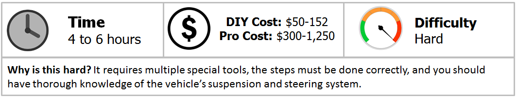
There will come a time when the ball joints on your vehicle are going to need replacing. On Jeeps, there are two main ball joints on each side of the vehicle. Both of these attach the axle housing to the steering knuckle. After some time, due to the the forces that they encounter through regular driving, they wear out and must be replaced. Now, before setting off to go get it done, it must be understood that this isn't the easiest repair that you could knock out on a weekend or a night after work. This repair requires many steps, many special tools, and a firm and thorough knowledge of your vehicle's suspension system. If you've never done this kind of repair before, it should be left up to someone who knows what they are doing. It's not easy by any means and can be frustrating due to the fact that suspension work requires a massive amount of patience. This article will go through a brief step-by-step on how to perform the repair, but there is no replacement for experience when it comes to a job like this.

Materials Needed
- Sockets sizes 12mm-21mm
- 13mm 12-point socket
- 36mm socket
- Ratchet
- Front suspension tool set
- Upper ball joint removal/installation tool
- Lower ball joint removal/installation tool
- Jack and jack stands
- Pliers
- Mallet
Before beginning, here are some pictures of the special tools required to complete this job:
Figure 2 is of a front suspension tool set. It has multiple tools that are all used on various different parts of the front suspension, usually for removing parts of it. There are a couple tools that will be required to perform this repair: one to remove the tie rod from the steering knuckle, one to remove the upper ball joint from the steering knuckle and one to remove the lower ball joint from the steering knuckle. You can usually rent this tool set at any major auto parts store through their tool rental program, or you can pick one up online.
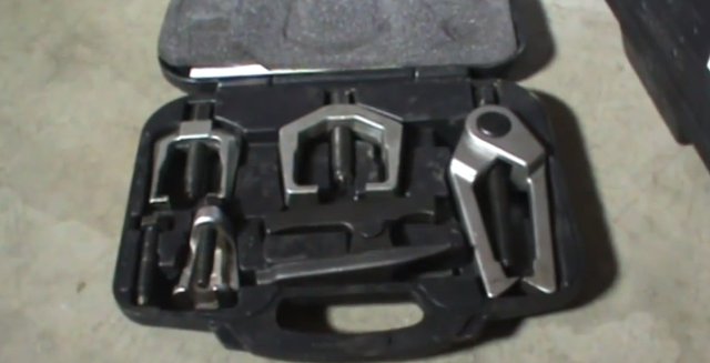
Figure 3 is of an upper ball joint removal/installation tool. As the name implies, it is required to remove and install the upper ball joint out of and into the axle housing. It comes with various different pieces that all fit different sizes of ball joints on different cars. You have to find which pieces will fit your application and set the tool up for that. It also can be rented from your local auto parts store or found online if you want to buy one.
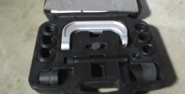
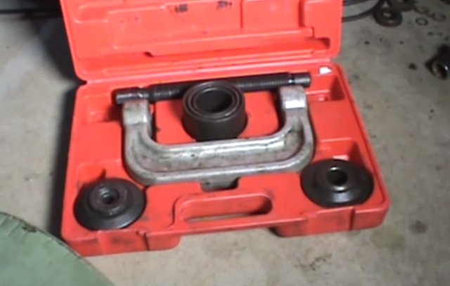
Figure 4 is of a lower ball joint removal/installation tool. Obviously it's for removing and installing the lower ball joint into and out of the axle housing. The reason why you need two different tools is because the ball joints are of different sizes. It's common for the lower ball joint to be a bit larger, and as you can see the tool itself is a bit larger. Again, you should be able to rent one of these from your local auto parts store or purchase one online if you'd like your own.
With all of this said, it's time to dig in to the how-to for those pesky ball joints.
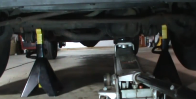
Step 1 – Place vehicle securely on jack stands
To begin, place the vehicle securely on jack stands. Since you don't need to have the front axle free to move for any reason, it is okay to place the jack stands under the front axle. This will help in ensuring that the vehicle is nice and secure.
Step 2 – Remove front wheels
Now go ahead and remove the front wheels. You will only need to remove the fronts because that is the area of the vehicle you will be working on.
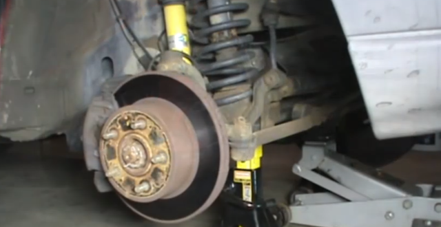
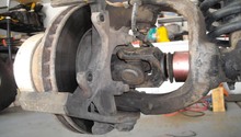
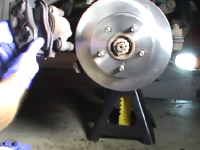
Step 3 – Remove brake caliper and brake rotor
To gain access to where the ball joints are, you will need to remove the brake assembly, caliper and rotor from the vehicle. The brake caliper is held onto the brake caliper mounting bracket by two bolts. Once you have removed the brake caliper, the rotor should be free to remove also. If the rotors have never been removed before, it is possible that there are tabbed washers that are threaded over the studs holding the rotor on. You can remove these and discard them. Because you are removing the caliper and rotor, this is a good time to inspect your brakes and possibly change them out when you go to put everything back together.
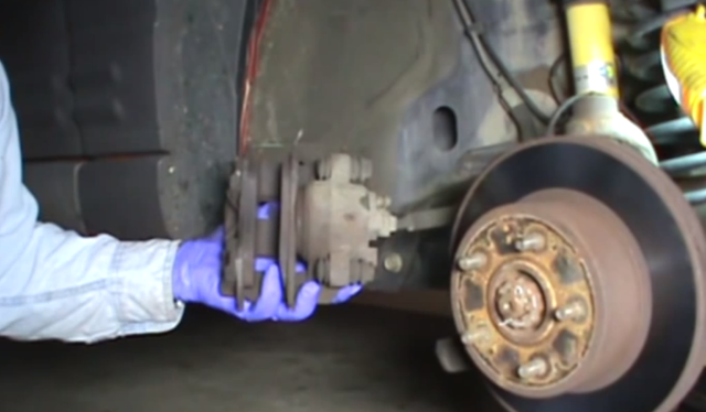
Figure 7. Remove brake caliper. 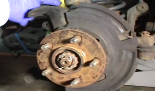
Figure 8. Remove brake rotor.
Step 4 – Remove hub assembly
The hub assembly on this version Jeep consists of the hub, axle, heat shield, and speed sensor. The hub is held onto the steering knuckle by three 13mm 12-point bolts. The hub is also attached to the axle and is held onto it by a 36mm nut. The 36mm nut has a protective cover with a cotter pin through it. First thing you will want to do is remove the three 13mm bolts, which you access from behind the hub. Then you can remove the axle nut cotter pin and axle nut cover. This will give you access to the 36mm nut, which you can then remove. Lastly, you will need to remove the speed sensor. After all this has been removed, you can then remove the hub and axle as one complete unit.
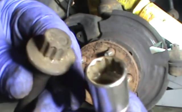
Figure 9. 13mm 12-point hub bolts. 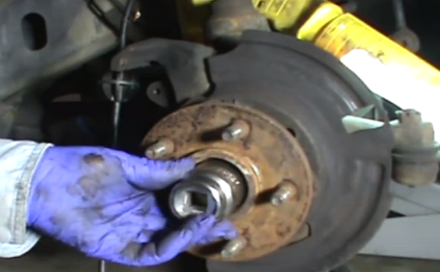
Figure 10. Axle nut removal.
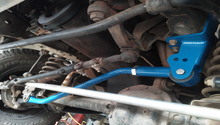
Step 5 – Remove tie rod from steering knuckle
Now that you have the hub assembly removed, you will need to remove the tie rod from the steering knuckle. This will allow you to move the steering knuckle around freely, helping you gain access to the ball joints and remove them from the steering knuckle. In order to remove the tie rod you will need to remove the cotter pin in the castle nut and then remove the castle nut. Then you will need to use one of the two jaw pullers out of the front suspension tool kit to pop out of the steering knuckle.

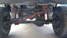
Step 6 – Remove steering knuckle
Now you should be able to rotate the steering knuckle and see that it will have to be removed in order to remove the ball joints from the axle housing. The ball joints are pressed into the steering knuckle, so just like with the tie rod you will have to use the tools that are in the front suspension tool kit in order to pop them out of place. Each of the tools in the kit can be used for different purposes, so you will have to determine by a little bit of trial and error which one will work best for you. Once you have both the ball joints removed from the steering knuckle, you can move the steering knuckle out of the way to give you access to the axle housing where the ball joints are pressed into.
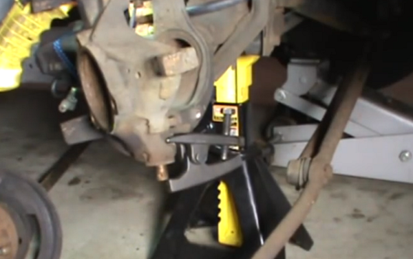
Figure 12. Remove lower ball joint from steering knuckle. 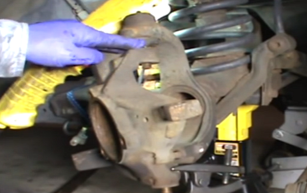
Figure 13. Remove upper ball joint from steering knuckle.
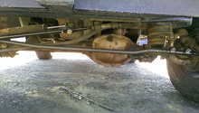
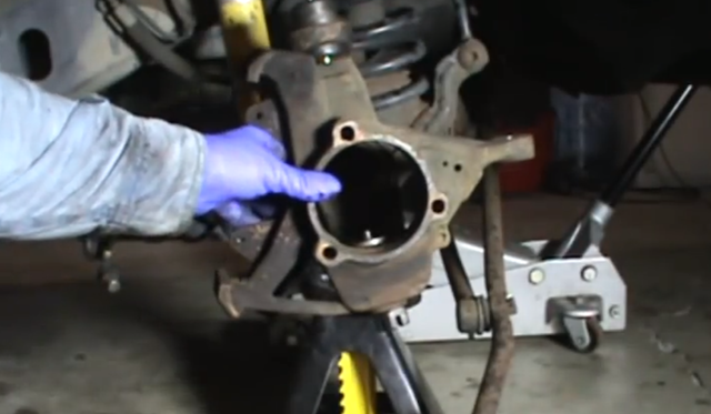
Step 7 – Remove ball joints from axle housing
The ball joints themselves are housed into the axle housing. Now that you have everything removed, you are finally at the point that you can actually access them and remove them from where they are pressed into. This is where you will need the upper as well as lower ball joint removal and installation tools. The way you setup the pieces of the tool is whether you are pressing it in or pressing it out. Each tool should have a set of instructions that will explain exactly how to set the tool up to do that. It's possible that each tool might be slightly different, so I won't go into the specifics here.
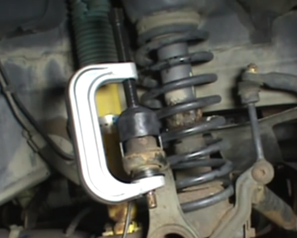
Figure 14. Remove upper ball joint from housing. 
Figure 15. Remove lower ball joint from housing.
Step 8 – Install new ball joints
Installing the new ball joints into the axle housing is the reverse of removing them. The same tools that you used to remove them will be used to press them back into the axle housing. You will just reverse the setup of them.
After you have pressed the new ball joints into the axle housing. Everything else goes back together as it was taken off. Be sure to use new cotter pins wherever you have removed them.
- Install the steering knuckle.
- Install the tie rod.
- Install the hub assembly, consisting of axle, heat shield, axle nut, three hub bolts, and speed sensor.

- Install the brake caliper and rotor.
- Install the wheels.
- Finally, place the vehicle back on the ground.
Featured Video: How to Replace Ball Joints
Related Discussions
- Ball Joint/U Joint Help - CherokeeForum.com
- Ball Joint-Axle Replacement - CherokeeForum.com
- Ball Joints - CherokeeForum.com
- Help Needed Identifying Ball Joints - CherokeeForum.com