
Gauge Cluster is out. I've tried ...


Thread Starter
Newbie
Joined: May 2014
Posts: 4
Likes: 0
From: Detroit
Year: 2000
Model: Cherokee
Engine: 4.0
I bought a 2000 Cherokee Sport 4.0 and the gauge cluster is out. I have already tried to clean the connectors and using dilectric grease. I also scraped pin 1 and 2 on the connector. this didnt work then I replaced the connector still doesnt work. I am getting a NO BUS on the message board. I have tested the cluster by pushing in the reset button then turned on ignition then released reset button. It goes thru its 10 second gauge check and everything works. Just gauges are out . turn signals light up as well as engine light. What am I to do next????

CF Veteran
Joined: Aug 2010
Posts: 8,357
Likes: 103
From: Canton, MI
Year: 1999
Model: Cherokee
Engine: 4.0
There have been cases where a NO BUS message was shown and no gauges worked because of corroded ground connections in the engine bay.
You might want to check/clean the ground points G100, G101, and the Firewall bonding strap, shown in the link below.
Detach the wire ring terminals at the ground points and scrub them clean using 3M #2 Scotch-Brite pads then reattach securely.
At G100 and the Firewall, sandpaper the sheetmetal contact points free of rust.
Try this and see if it helps.
Ground points: Refer to post #49.
https://www.cherokeeforum.com/f2/gre...e-6558/index4/

Senior Member
Joined: Feb 2012
Posts: 864
Likes: 4
From: Arlington, Texas
Year: 1998
Model: Cherokee
Engine: 4.0
Mine used to screw up all the time. Try this... Get it running and with the gauges NOT working take your hand and gently but steadily push in on the gauge cluster like you're trying to push it toward the engine bay. You can use about as much pressure as you want, so long as it's not enough to crack the clear plastic lens. If they come on while you press, but go off when you let go, you'll need to do what I did.
Take the cluster out. Buy some thin 1/8" washers and wedge them in between the two green connectors and the plastic undercarriage of the dash to try and move those green connectors more toward the drivers seat. I know that's the worst description ever, but it will make more sense once you're looking at everything. Since I did this, my gauges have worked without fail.
Take the cluster out. Buy some thin 1/8" washers and wedge them in between the two green connectors and the plastic undercarriage of the dash to try and move those green connectors more toward the drivers seat. I know that's the worst description ever, but it will make more sense once you're looking at everything. Since I did this, my gauges have worked without fail.
Trending Topics
CF Veteran
Joined: Aug 2010
Posts: 8,357
Likes: 103
From: Canton, MI
Year: 1999
Model: Cherokee
Engine: 4.0
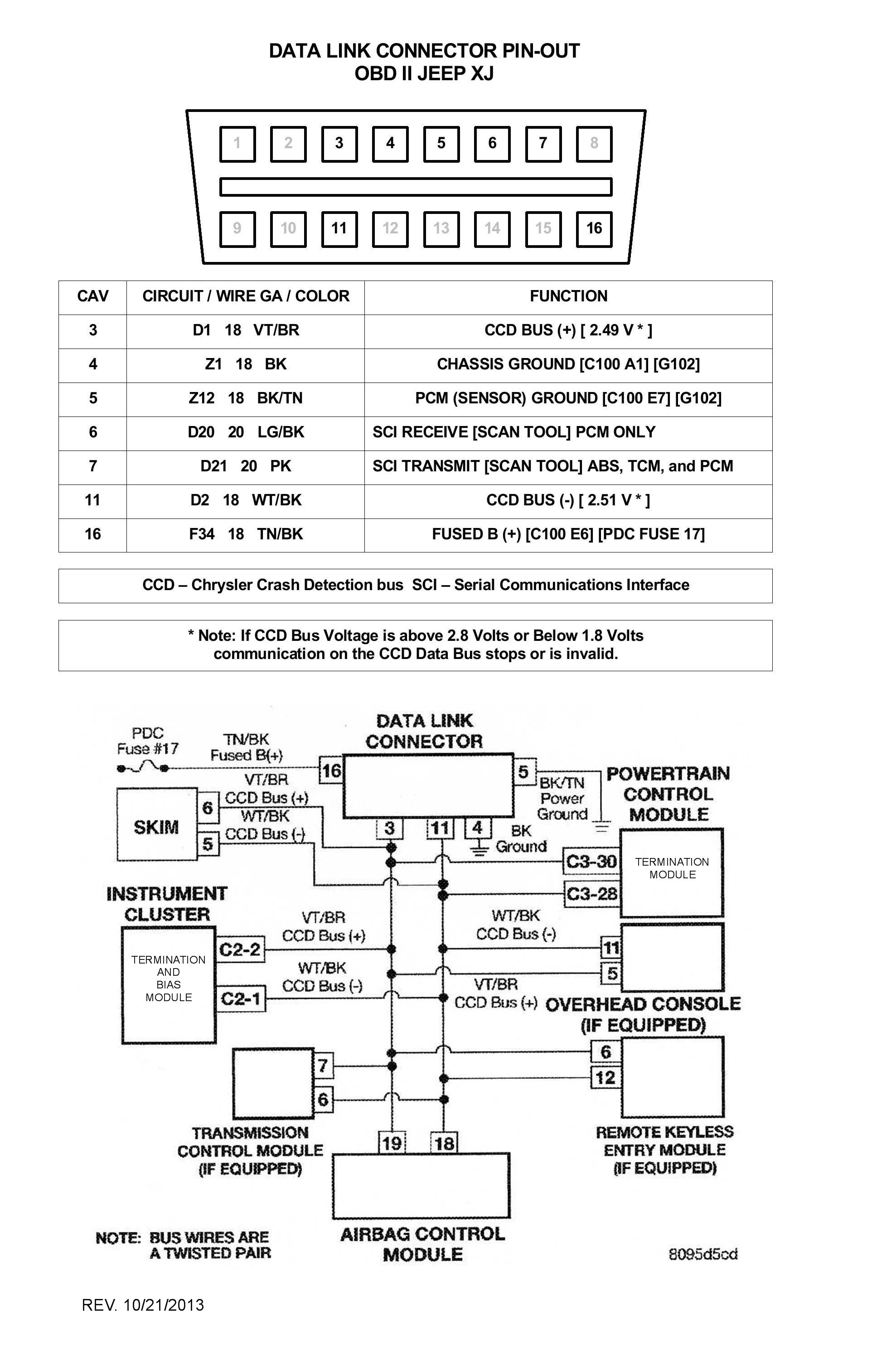
There are two Termination Resistors in the CCD Bus circuit, one in the instrument Cluster and one in the PCM. Each termination resistor will drop the 5 volt bias voltage generated by the Instrument cluster to around 2.51 volts in the CCD Bus +/- circuits. Each terminaion resistor measurs 120 Ohms. The two resistors in parallel will be 60 Ohms.
Using a digital Ohmmeter measure the resistance in the CCD Bus circuit at the Data Link Connector. See diagram below.
Disconnect the Battery negative post connector.
Mesure the resistance betwee DLC pin cavities 3 and 11. You should see 60 Ohms. If you see 120 Ohms, one of the termination resistors is out.
If you see 120 Ohms, remove the Instrument Cluster and read from pin cavities 3 and 11 again. If you see 120 Ohms, the PCM termination resistor is good. If you see zero Ohms, the PCM resistor is shot. (unlikely).
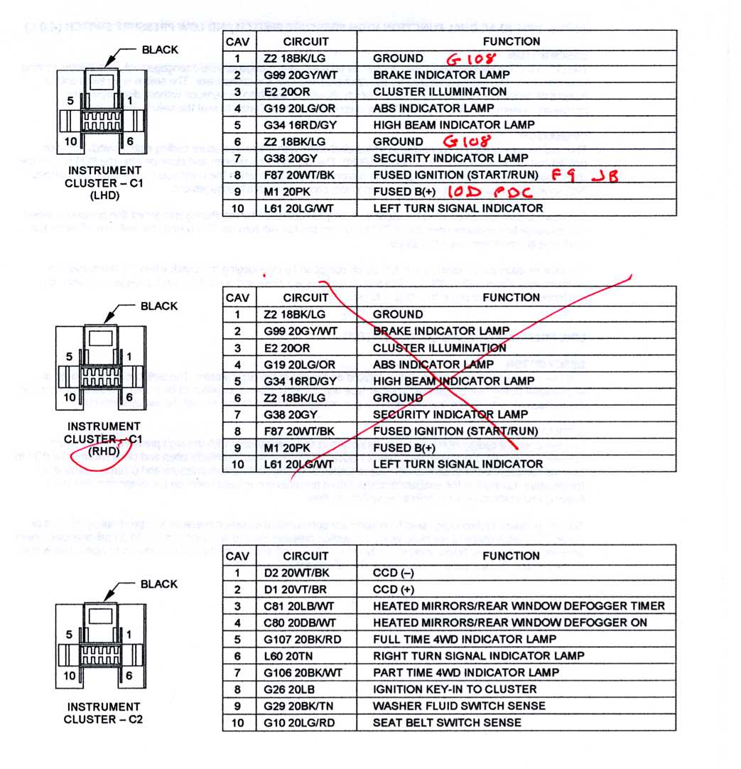
Next you will need to measure the resistance of the Instrument cluster Termination Resistor at the C2 connector on the Instrument Cluster. See pic below. C2 is the docking connector on your right as you look at the dash from the driver seat.
Knowing that the pinouts below are the mirror image of the Instrument Cluster, measure the resistance between pins 1 and 2 or connector C2. You should see 120 Ohms. If you do the Termination Resistor is okay. If not the Instrument cluster must be replaced.
Do this and check back
Instrument Clustor docking connectors pinout (mirror image of the connectors on the cluster).
Using a digital Ohmmeter measure the resistance in the CCD Bus circuit at the Data Link Connector. See diagram below.
Disconnect the Battery negative post connector.
Mesure the resistance betwee DLC pin cavities 3 and 11. You should see 60 Ohms. If you see 120 Ohms, one of the termination resistors is out.
If you see 120 Ohms, remove the Instrument Cluster and read from pin cavities 3 and 11 again. If you see 120 Ohms, the PCM termination resistor is good. If you see zero Ohms, the PCM resistor is shot. (unlikely).
Next you will need to measure the resistance of the Instrument cluster Termination Resistor at the C2 connector on the Instrument Cluster. See pic below. C2 is the docking connector on your right as you look at the dash from the driver seat.
Knowing that the pinouts below are the mirror image of the Instrument Cluster, measure the resistance between pins 1 and 2 or connector C2. You should see 120 Ohms. If you do the Termination Resistor is okay. If not the Instrument cluster must be replaced.
Do this and check back
Instrument Clustor docking connectors pinout (mirror image of the connectors on the cluster).

Thread
Thread Starter
Forum
Replies
Last Post
stimp774
Stock XJ Cherokee Tech. All XJ Non-modified/stock questions go here
20
Apr 16, 2017 03:46 PM
steamin53
Stock XJ Cherokee Tech. All XJ Non-modified/stock questions go here
2
Sep 13, 2015 04:31 AM
Chick-N-Picker
Stock XJ Cherokee Tech. All XJ Non-modified/stock questions go here
2
Sep 7, 2015 07:56 PM
sikkev
Stock XJ Cherokee Tech. All XJ Non-modified/stock questions go here
0
Sep 5, 2015 11:33 PM
Currently Active Users Viewing This Thread: 1 (0 members and 1 guests)