


 Sep 18, 2015, 01:58 PM
Last edit by: IB Advertising
See related guides and technical advice from our community experts:
Browse all: Jeep Cherokee XJ Cooling System Guides
- Jeep Cherokee 1984-2001: How to Install Electric Fan
Step by step instructions for do-it-yourself repairs.
Browse all: Jeep Cherokee XJ Cooling System Guides

Electric fan not working.....

CF Veteran
Joined: Aug 2010
Posts: 8,357
Likes: 103
From: Canton, MI
Year: 1999
Model: Cherokee
Engine: 4.0

It had seemed to me you guys are saying about the same thing.
Ambient temperatures are not measured by the PCM with regards to A/c compressor operation. Low ambient temperatures will cause the fan to cycle on an off only because of the effect that cold air has on the refrigerant
And;
contacts to open. This is due to
the pressure/temperature relationship of the refrigerant
in the system.
True, temperature isn't what makes mercury rise in a thermometer, it's actually the pressure that does it.
Or maybe I'm completely missing something. Anyway I just wanted to chime in and thank Ken for helping clarify the SPDT, (Single Pole, Double Throw), relay where all the action converges. At that socket you can, *Power the fan directly, *check for power to both the fan, and the relay coil, *and check that the PCM is grounding the relay to activate the fan.
Ambient temperatures are not measured by the PCM with regards to A/c compressor operation. Low ambient temperatures will cause the fan to cycle on an off only because of the effect that cold air has on the refrigerant
And;
contacts to open. This is due to
the pressure/temperature relationship of the refrigerant
in the system.
True, temperature isn't what makes mercury rise in a thermometer, it's actually the pressure that does it.
Or maybe I'm completely missing something. Anyway I just wanted to chime in and thank Ken for helping clarify the SPDT, (Single Pole, Double Throw), relay where all the action converges. At that socket you can, *Power the fan directly, *check for power to both the fan, and the relay coil, *and check that the PCM is grounding the relay to activate the fan.
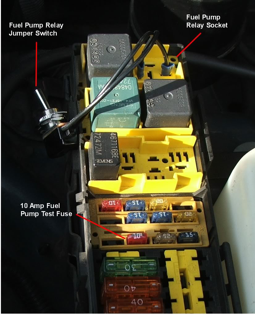
Here's the fuel pump test set up. I installed a 10 Amp fuse in place of the normal fuel pump 15 Amp fuse. This set up takes the place of the Amp draw test apparatus shown in the FSM to test for a 10 Amp (or less) Amp draw from the pump. The 10 Amp fuse didn't blow so I assume my pump is drawing less than 10 Amps. Kind of ghetto I know, but it works.



CF Veteran
Joined: Aug 2011
Posts: 10,489
Likes: 24
From: Nor-Cal Coast
Year: 90,84
Model: Cherokee
Engine: 4.0,2.5
Djb, my main thought was its pretty handy to be able to check so much at the relay socket.
Ken, Cool. I live off grid. Got ammeters everywhere. Ghetto? You wanna talk ghetto? How about, hold the kill switch for your Onan down to run the fuel pump to prime it, (and kill it), so on start she kicks right in? Using only the original control wiring, from all, (four), switch locations. These fit OK in the control box.
Ken, Cool. I live off grid. Got ammeters everywhere. Ghetto? You wanna talk ghetto? How about, hold the kill switch for your Onan down to run the fuel pump to prime it, (and kill it), so on start she kicks right in? Using only the original control wiring, from all, (four), switch locations. These fit OK in the control box.
CF Veteran
Joined: Aug 2010
Posts: 8,357
Likes: 103
From: Canton, MI
Year: 1999
Model: Cherokee
Engine: 4.0
Djb, my main thought was its pretty handy to be able to check so much at the relay socket.
Ken, Cool. I live off grid. Got ammeters everywhere. Ghetto? You wanna talk ghetto? How about, hold the kill switch for your Onan down to run the fuel pump to prime it, (and kill it), so on start she kicks right in? Using only the original control wiring, from all, (four), switch locations. These fit OK in the control box.
Ken, Cool. I live off grid. Got ammeters everywhere. Ghetto? You wanna talk ghetto? How about, hold the kill switch for your Onan down to run the fuel pump to prime it, (and kill it), so on start she kicks right in? Using only the original control wiring, from all, (four), switch locations. These fit OK in the control box.
I love ghetto tools. Especially ones that are well made, like the one I'm looking at in your photo.
Not too fond of Bubba tools however. That being said, I have made some Ghetto/Bubba crossover tools.
I made a neat crossover tool to install the rear output shaft seal on a transfer case. I'll try and take a photo of it.
CF Veteran
Joined: Aug 2011
Posts: 10,489
Likes: 24
From: Nor-Cal Coast
Year: 90,84
Model: Cherokee
Engine: 4.0,2.5
Ken; I don't know that I need anything installed in my rear output, but let's see it! Does it look like a can crusher? And thanks ^. All soldered....took tooo long.
Djb/Roc-Jeep..At the risk of just further confusing things...At the relay socket pictured in post #10. When the PCM grounds post 85, current flows through the relay coil from 86. The coil becomes an electromagnet to pull the contacts closed which connect power through from post 30 to 87 where it goes to the fan. So right there with a jumper you could test the fan and it's wires, by energizing 87. Also with a meter you could check for power at 30 & 86, (and so there fuses), and also see if 85 is being grounded by the PCM.
The middle, 87a is hot when it's off, then off when the relay is energized. I don't think it's used here.
I once had a similar fan in a Tempo give me a fit. Worked fine testing it, but would blow the fuse often. Everything was fine! I finally figured out it was drawing way too much current. (Ken's gadget above^, would have caught that). Fan turns free, blows great, just draws too much amperage.
As far as the other...it seemed to me those guys essentially agreed. Although the PCM might not specifically measure that temperature, it can infer it via the low gas pressure with the identical result. I don't know for sure.
Djb/Roc-Jeep..At the risk of just further confusing things...At the relay socket pictured in post #10. When the PCM grounds post 85, current flows through the relay coil from 86. The coil becomes an electromagnet to pull the contacts closed which connect power through from post 30 to 87 where it goes to the fan. So right there with a jumper you could test the fan and it's wires, by energizing 87. Also with a meter you could check for power at 30 & 86, (and so there fuses), and also see if 85 is being grounded by the PCM.
The middle, 87a is hot when it's off, then off when the relay is energized. I don't think it's used here.
I once had a similar fan in a Tempo give me a fit. Worked fine testing it, but would blow the fuse often. Everything was fine! I finally figured out it was drawing way too much current. (Ken's gadget above^, would have caught that). Fan turns free, blows great, just draws too much amperage.
As far as the other...it seemed to me those guys essentially agreed. Although the PCM might not specifically measure that temperature, it can infer it via the low gas pressure with the identical result. I don't know for sure.



Newbie
Joined: Jun 2025
Posts: 1
Likes: 0
4.0L?
Is this for a 4.0 L? I only ask because the picture quoted for the relay 85 and 86 are flipped on my relay and I’m definitely having this issue.
If you tried the connector jumping shown in post #6 and the fan still won't turn on, it may be an open in the ground wire from the PCM to the fan relay coil. The fan relay coil is powered through the start-run bus fuse (11 in your case) at relay socket #86. THe PCM provides a ground to this coil at relay socket #85. When the PCM receives an AC select signal or a high coolant temp signal it will provide a ground to the coil, pulling the relay contacts closed and proving power, from the 40 Amp fuse, to the fan.
If the PCM ground wire (C27 18 DB/PK) from pin C2 of PCM connector C3) is open, no ground will be provided to the fan relay coil.
Here's a pic of the relay socket configuration:
Attachment 376716
Check these pin numbers against the pin numbers on the bottom of your fan relay to confirm this is the type relay you have.
To troubleshoot an open in the PCM ground wire you'll need to detach PCM connector C3, remove the fan relay, and using an Ohmmeter, read between relay socket 85 and PCM C3 socket C2. You should read continuity.
Here's C3. Disregard the darkened pins, that was for a different problem. If this is not your C3 pin configuration let me know. Shown is a '99 C3 pinout. The '97 ('98?) C3 pinout is the same, as far as the cavity (CAV)numbering list goes, but it the illustration of the connector cavity numbering is different. A Chrysler thing I guess. You're looking for an 18 Ga. Dark Blue/Pink wire.
Attachment 376717
If the PCM ground wire (C27 18 DB/PK) from pin C2 of PCM connector C3) is open, no ground will be provided to the fan relay coil.
Here's a pic of the relay socket configuration:
Attachment 376716
Check these pin numbers against the pin numbers on the bottom of your fan relay to confirm this is the type relay you have.
To troubleshoot an open in the PCM ground wire you'll need to detach PCM connector C3, remove the fan relay, and using an Ohmmeter, read between relay socket 85 and PCM C3 socket C2. You should read continuity.
Here's C3. Disregard the darkened pins, that was for a different problem. If this is not your C3 pin configuration let me know. Shown is a '99 C3 pinout. The '97 ('98?) C3 pinout is the same, as far as the cavity (CAV)numbering list goes, but it the illustration of the connector cavity numbering is different. A Chrysler thing I guess. You're looking for an 18 Ga. Dark Blue/Pink wire.
Attachment 376717

Thread
Thread Starter
Forum
Replies
Last Post
jmsummers2012
Stock XJ Cherokee Tech. All XJ Non-modified/stock questions go here
56
Jun 12, 2025 02:04 AM
scatgo
Stock XJ Cherokee Tech. All XJ Non-modified/stock questions go here
14
Mar 22, 2021 09:56 AM
LittleRed94
Stock XJ Cherokee Tech. All XJ Non-modified/stock questions go here
5
Oct 6, 2015 08:09 PM
Sandyman
Stock XJ Cherokee Tech. All XJ Non-modified/stock questions go here
10
Sep 29, 2015 06:33 PM
Josh Meck
Stock XJ Cherokee Tech. All XJ Non-modified/stock questions go here
1
Sep 27, 2015 03:16 PM
Currently Active Users Viewing This Thread: 1 (0 members and 1 guests)
