
Cherokee Fail- Runs/starts cold then dies???


Thread Starter
Newbie
Joined: Mar 2014
Posts: 5
Likes: 0
Year: 1987
Model: Cherokee
Engine: straight 6
Hello i have a 1987 Jeep loredo with a straight 6 , will start cold run for 15 minutes then without a sign will shut off.if I wait 10 minutes it will start and run for another 15 minutes and shut off i replaced the CKP, the ignition coil and lines and sparkplugs. any ideas where to check next ?

::CF Moderator::
Joined: Aug 2011
Posts: 43,971
Likes: 1,579
From: Prescott, Az
Year: 1990
Model: Cherokee (XJ)
Engine: 4.0
Hello i have a 1987 Jeep loredo with a straight 6 , will start cold run for 15 minutes then without a sign will shut off.if I wait 10 minutes it will start and run for another 15 minutes and shut off i replaced the CKP, the ignition coil and lines and sparkplugs. any ideas where to check next ?
CF Veteran
Joined: Sep 2011
Posts: 4,172
Likes: 4
From: Riviera, Texas
Year: 1998 Sport
Model: Cherokee
Engine: 4.0
Like allevolution said check your spark. Make sure that it is a strong blue spark. Any other color is not sufficient for the 4.0. Also check the fuel pressure at the fuel rail with a mechanical pressure gauge. The pressure for your year should be 39psi +or- 5psi. Also where did you get your CPS from? After market ones are known to be bad right out of the box and if they do work the have a very short life span. If it is an aftermarket one you may want to consider replacing it with an OEM one from the dealer.
::CF Moderator::
Joined: Aug 2011
Posts: 43,971
Likes: 1,579
From: Prescott, Az
Year: 1990
Model: Cherokee (XJ)
Engine: 4.0
Like allevolution said check your spark. Make sure that it is a strong blue spark. Any other color is not sufficient for the 4.0. Also check the fuel pressure at the fuel rail with a mechanical pressure gauge. The pressure for your year should be 39psi +or- 5psi. Also where did you get your CPS from? After market ones are known to be bad right out of the box and if they do work the have a very short life span. If it is an aftermarket one you may want to consider replacing it with an OEM one from the dealer.
CF Veteran
Joined: Sep 2011
Posts: 4,172
Likes: 4
From: Riviera, Texas
Year: 1998 Sport
Model: Cherokee
Engine: 4.0

::CF Moderator::
Joined: Aug 2011
Posts: 43,971
Likes: 1,579
From: Prescott, Az
Year: 1990
Model: Cherokee (XJ)
Engine: 4.0
Trending Topics
Thread Starter
Newbie
Joined: Mar 2014
Posts: 5
Likes: 0
Year: 1987
Model: Cherokee
Engine: straight 6
I appreciate all your inputs , i recently attempted to clean the c101 and the jeep started running worse so i decided to try and bypass the whole c101 all together and i noticed on the side closest to the passanger side has a couple wires that dont match up without leaving wire on the terminal to double check , i tried to read the schematic and placed a orng wire to a gray , and every where i looked the extra blk wire was ground. once connected the jeep ran a bit rough then started spitting fuel.. note that since i couldnt figure out wich wire the black originally went to i ran it straight to a grounding point and without doing so it wouldnt have start. im assuming that the ground must be regulated to prevent over pressure too the fuel line.
, i tried to read the schematic and placed a orng wire to a gray , and every where i looked the extra blk wire was ground. once connected the jeep ran a bit rough then started spitting fuel.. note that since i couldnt figure out wich wire the black originally went to i ran it straight to a grounding point and without doing so it wouldnt have start. im assuming that the ground must be regulated to prevent over pressure too the fuel line.
::CF Moderator::
Joined: Aug 2011
Posts: 43,971
Likes: 1,579
From: Prescott, Az
Year: 1990
Model: Cherokee (XJ)
Engine: 4.0
Here's my most recent write-up. Post 27 in the link.
C101 connector elimination
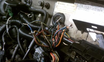
Unbolt the 2 halves of the C101 using a �� socket. On each half there is a plastic cover where the wires enter. They are removable but you'll probably end up busting them off. Lightly bolt the C101 back together, away from the firewall. Peel back the split-loom covering from the body side of the C101 connector down to where the harness splits and goes toward the firewall, pretty much below the MAP sensor. On the engine side, remove the split loom about the same distance. See first photo.
Now you can see from one side of the C101 to the other. Beginning at the top row, closest to the motor, be absolutely sure you cut the matching wires on each side of the connector off to about 1/2 inch. This will allow you to verify the original position of each wire color in case of mistakes or confusion. CUT AND SOLDER ONE PAIR AT A TIME. The wires may be wound a bit in their looms. See the first photo. Get them unwound neatly and do the following, ONE AT A TIME.
Slide your shrink tube over one wire. In a well ventilated area, solder the wires together and then slide the shrink tubing over the solder joint. Heat the shrink tubing so it seals your completed solder joint. Keep going until you've done all 22 or so connections.
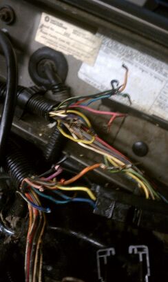
Both sides of the C101 connection have a wire that is brown with white tracer. Follow each of these wires back until you come to a point where three wires are crimped together. See the second photo.
What you want to do here is cut the crappy factory crimp out of each set of three and bring both sets of three wires together and solder them together, using shrink tubing as well. All 6 wires. These particular wires will not end up in your normal C101 elimination loom. See the third photo.
After all the soldering and shrink tubing is done, bundle the wires together in a new piece of 3/4" split loom. Tape it up and secure it to the C101 connector's original bolt hole or somewhere else along the firewall so it will be protected. See the third photo.
Revised 03-06-14
C101 connector elimination
Unbolt the 2 halves of the C101 using a �� socket. On each half there is a plastic cover where the wires enter. They are removable but you'll probably end up busting them off. Lightly bolt the C101 back together, away from the firewall. Peel back the split-loom covering from the body side of the C101 connector down to where the harness splits and goes toward the firewall, pretty much below the MAP sensor. On the engine side, remove the split loom about the same distance. See first photo.
Now you can see from one side of the C101 to the other. Beginning at the top row, closest to the motor, be absolutely sure you cut the matching wires on each side of the connector off to about 1/2 inch. This will allow you to verify the original position of each wire color in case of mistakes or confusion. CUT AND SOLDER ONE PAIR AT A TIME. The wires may be wound a bit in their looms. See the first photo. Get them unwound neatly and do the following, ONE AT A TIME.
Slide your shrink tube over one wire. In a well ventilated area, solder the wires together and then slide the shrink tubing over the solder joint. Heat the shrink tubing so it seals your completed solder joint. Keep going until you've done all 22 or so connections.
Both sides of the C101 connection have a wire that is brown with white tracer. Follow each of these wires back until you come to a point where three wires are crimped together. See the second photo.
What you want to do here is cut the crappy factory crimp out of each set of three and bring both sets of three wires together and solder them together, using shrink tubing as well. All 6 wires. These particular wires will not end up in your normal C101 elimination loom. See the third photo.
After all the soldering and shrink tubing is done, bundle the wires together in a new piece of 3/4" split loom. Tape it up and secure it to the C101 connector's original bolt hole or somewhere else along the firewall so it will be protected. See the third photo.
Revised 03-06-14
Thread Starter
Newbie
Joined: Mar 2014
Posts: 5
Likes: 0
Year: 1987
Model: Cherokee
Engine: straight 6
Here's my most recent write-up. Post 27 in the link.
C101 connector elimination
Unbolt the 2 halves of the C101 using a �� socket. On each half there is a plastic cover where the wires enter. They are removable but you'll probably end up busting them off. Lightly bolt the C101 back together, away from the firewall. Peel back the split-loom covering from the body side of the C101 connector down to where the harness splits and goes toward the firewall, pretty much below the MAP sensor. On the engine side, remove the split loom about the same distance. See first photo.
Now you can see from one side of the C101 to the other. Beginning at the top row, closest to the motor, be absolutely sure you cut the matching wires on each side of the connector off to about 1/2 inch. This will allow you to verify the original position of each wire color in case of mistakes or confusion. CUT AND SOLDER ONE PAIR AT A TIME. The wires may be wound a bit in their looms. See the first photo. Get them unwound neatly and do the following, ONE AT A TIME.
Slide your shrink tube over one wire. In a well ventilated area, solder the wires together and then slide the shrink tubing over the solder joint. Heat the shrink tubing so it seals your completed solder joint. Keep going until you've done all 22 or so connections.
Both sides of the C101 connection have a wire that is brown with white tracer. Follow each of these wires back until you come to a point where three wires are crimped together. See the second photo.
What you want to do here is cut the crappy factory crimp out of each set of three and bring both sets of three wires together and solder them together, using shrink tubing as well. All 6 wires. These particular wires will not end up in your normal C101 elimination loom. See the third photo.
After all the soldering and shrink tubing is done, bundle the wires together in a new piece of 3/4" split loom. Tape it up and secure it to the C101 connector's original bolt hole or somewhere else along the firewall so it will be protected. See the third photo.
Revised 03-06-14
Thread Starter
Newbie
Joined: Mar 2014
Posts: 5
Likes: 0
Year: 1987
Model: Cherokee
Engine: straight 6
thats all great information, and now that ive read it through correctly i understand what i could have done to prevent my huge mess up,,,  But i didnt leave enough wire on the original c101 to verify which wire went where///: I dont know i guess ill look up some wire schematics and follow each wire?!?!?
Thread Starter
Newbie
Joined: Mar 2014
Posts: 5
Likes: 0
Year: 1987
Model: Cherokee
Engine: straight 6
::CF Moderator::
Joined: Aug 2011
Posts: 43,971
Likes: 1,579
From: Prescott, Az
Year: 1990
Model: Cherokee (XJ)
Engine: 4.0

Thread
Thread Starter
Forum
Replies
Last Post
XJ ONLY
Stock XJ Cherokee Tech. All XJ Non-modified/stock questions go here
8
Jan 26, 2019 06:30 PM
Rotorhead
Stock XJ Cherokee Tech. All XJ Non-modified/stock questions go here
10
Aug 31, 2015 12:41 PM
Jethro4days
Stock XJ Cherokee Tech. All XJ Non-modified/stock questions go here
18
Aug 25, 2015 08:42 PM
bfh_american
Stock XJ Cherokee Tech. All XJ Non-modified/stock questions go here
10
Aug 22, 2015 12:15 PM
Currently Active Users Viewing This Thread: 1 (0 members and 1 guests)