


So I bought & Installed an S Series 6 phase 170 amp MechMan alternator. The alt is properly grounded and powered by 1/0 cables, but the plug is different from my stock plug.
In one picture you can see the stock connector that has 4 connections that bolt to the back of the stock alternator & a pic of the back of the stock alt. In the other pic, you can see the MechMan alt with an oval sized tan plug with 2 prongs inside of it.
I sent an email to the company and figured I'd put up a thread here as well to see if anyone here has installed one & can speak on this. Any help would be appreciated!


You need a matching pigtail. Looks similar to the Durango alt I put on mine. Go to the local JY, find a Durango, cut the pigtail off and splice it in.
Member
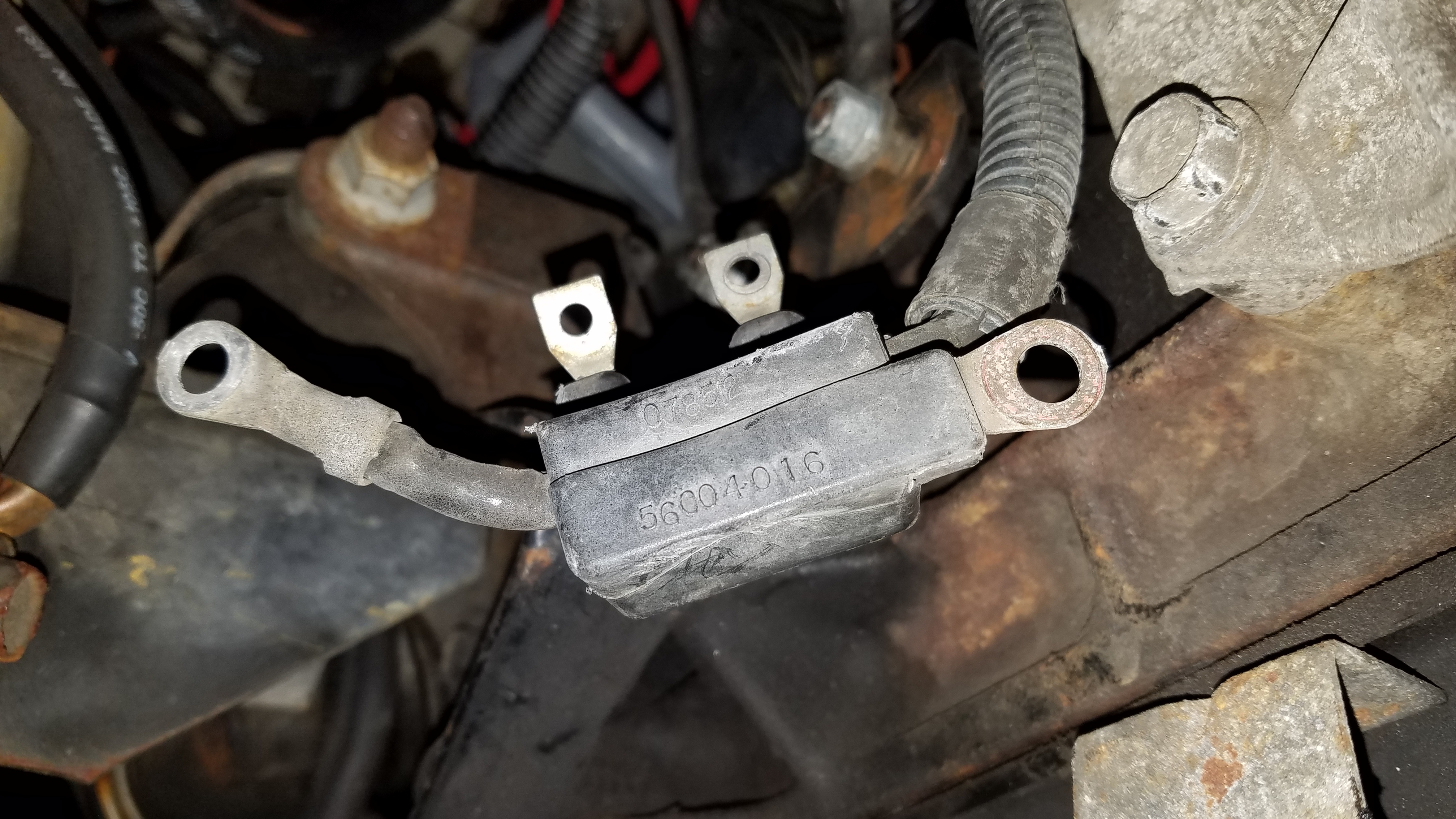
Regarding the stock connector with 4 connections in the first picture, can anyone explain what the connections do?
CF Veteran
To start with it's the wrong application for that. Wasn't the proper application available? Unless it's unavailable, I would have exchanged it for the proper application to fit that harness. Now once you change this, you will have to mess with improper application/model/year numbers from now on with that alternator.
Quote:
The original alt is externally regulated by a rectifier diode, encased inside that plastic piece. The 2 small pigtails on the outside are grounds, and the two small terminals in the middle are the field wires that go to the PCM.Originally Posted by TimV
Regarding the stock connector with 4 connections in the first picture, can anyone explain what the connections do?
The newer alt is INTERNALLY regulated, so the diode on the original harness needs to go away, and the field wires get spliced onto the pigtail for the new alt.
CF Veteran
Quote:
The newer alt is INTERNALLY regulated, so the diode on the original harness needs to go away, and the field wires get spliced onto the pigtail for the new alt.
I appreciate explanation that very much. I understand completely now. Originally Posted by roninofako
The original alt is externally regulated by a rectifier diode, encased inside that plastic piece. The 2 small pigtails on the outside are grounds, and the two small terminals in the middle are the field wires that go to the PCM.The newer alt is INTERNALLY regulated, so the diode on the original harness needs to go away, and the field wires get spliced onto the pigtail for the new alt.

How prone is that external diode to failure? Forcing a whole new pigtail to be spliced in?
Quote:
How prone is that external diode to failure? Forcing a whole new pigtail to be spliced in?
It isn't that it's prone to failure...you've now modded the system with an alt that internally regulates what goes to the PCM. Which is what determines how the PCM regulates voltage in the system. You remove the alt with the external regulation, and add the alt with internal regs. Nothing really changes, except location of the diode. Just make sure you get the field wires right. A simple schematic from a FSM makes this a breeze.Originally Posted by Bugout4x4
I appreciate explanation that very much. I understand completely now. How prone is that external diode to failure? Forcing a whole new pigtail to be spliced in?
Bottom line is you need to know what you're doing when tackling a mod like this. I had to hunt several things to get mine right. 5-90 used to have a great resource with his site. Don't even know if it's still up, he kinda dropped off the face of the earth. Everything I needed to know, I got from his website. Damn shame.
Don't even know if his website is still up. Last I had heard, he had taken several people's money for cables...and never delivered. After a dry spell, Neal AKA Mean Lemons, took over on making cables...but 5-90's site had some GREAT reading on there. Again, sad loss.
Just went to his old site...it is unfortunately gone.
So sad. There was a WEALTH of info there.
So sad. There was a WEALTH of info there.
CF Veteran
Quote:
So sad. There was a WEALTH of info there.
Bummer, I hate losing good sites like that... lost one just the other day I used to reference to all the time.Originally Posted by roninofako
Just went to his old site...it is unfortunately gone.So sad. There was a WEALTH of info there.
I was actually curious about the diode in the factory setup? I can't help but think that this design to put part of the alternator system, ie the diode, in an external pigtail is absolutely ignorant. lol
CF Veteran
Quote:
So sad. There was a WEALTH of info there.
Just use the Internet Archive Wayback Machine:Originally Posted by roninofako
Just went to his old site...it is unfortunately gone.So sad. There was a WEALTH of info there.
https://web.archive.org/web/20160915192323/http://www.kelleyswip.com:80/

Senior Member
I think my 85 2.5L has that setup with external diode, if that is bad could that be why my battery goes flat after a week if I don't start it up?
CF Veteran
Quote:
This was my curiosity. Because a diode is nothing but a one way check valve for juice. And when they go bad it will allow back flow and do exactly what you are asking here.Originally Posted by jedijeb
I think my 85 2.5L has that setup with external diode, if that is bad could that be why my battery goes flat after a week if I don't start it up?
Quote:
The newer alt is INTERNALLY regulated, so the diode on the original harness needs to go away, and the field wires get spliced onto the pigtail for the new alt.
I found the MechMan pigtail which was in the box, lol. I I called Mechman to see how to wire it up. They told me to connect the two wires off of their pigtail to the two inner wires on the stock harness. They said it didn't matter which wire was connected to which .Originally Posted by roninofako
The original alt is externally regulated by a rectifier diode, encased inside that plastic piece. The 2 small pigtails on the outside are grounds, and the two small terminals in the middle are the field wires that go to the PCM.The newer alt is INTERNALLY regulated, so the diode on the original harness needs to go away, and the field wires get spliced onto the pigtail for the new alt.
They also told me to tape off the outer 2 wires on the stock harness which I'm not so sure that's accurate. I believe they are grounds because if you look at the stock alternator, those 2 outer wires were attached to the outer basket and doing that means those wires are grounds!....?
What do you guys sell think??
Thanks!