When you click on links to various merchants on this site and make a purchase, this can result in this site earning a commission. Affiliate programs and affiliations include, but are not limited to, the eBay Partner Network.
This write-up covers installing front turn signal and side marker LEDs on my 93 XJ. This will likely apply to 87-01 model years however the location/wire colors may be different so consult with your year’s wiring diagram to double check.
Disclaimer: Follow this guide at your own risk. Altering or replacing the factory wiring has the potential to cause short circuits and fires if you do not understand what you are doing or make a mistake. Always disconnect your battery before doing any wiring and double-check your work before reconnecting. Do not attempt this if you are not comfortable with vehicle wiring.
Tools Needed:
Crimping tool + crimps or soldering iron + solder
Utility knife
Electrical tape
Adhesive lined heat shrink
Basic socket set
Screwdrivers
FSM w/ wiring diagrams
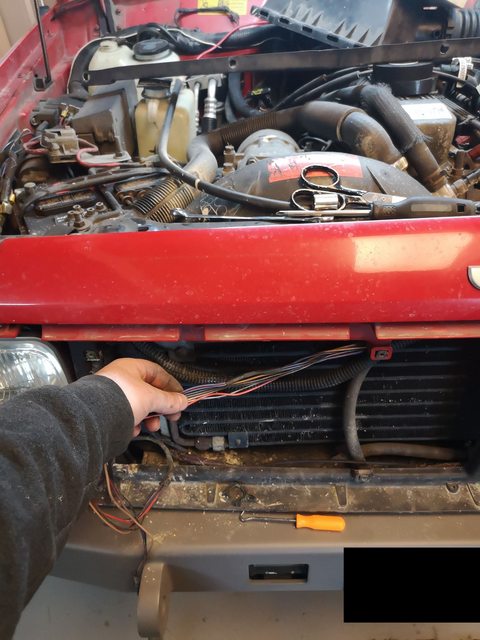
You will need to be able to remove the air filter box, side-markers, front corner trim, turn signal housings, and the center grille to access all of the necessary wiring.
Problems with installing LEDs in the XJ:
The first issue with installing LEDs in the front turn signals is that the LED is wired different internally, unlike the factory 1157 incandescent bulb which has two separate incandescent elements (circuits), the LEDs are all on one circuit. One of the terminals will give you full brightness, and the other half brightness via an internal resistor in the bulb. This means when you install an LED and have both the parking lights/headlights on and turn signal it will never go to the half brightness mode, as the headlight circuit is back-feeding into the turn signal circuit. This is common to any vehicle that uses these bulbs and switches to LEDs.
The second issue is the way the side-marker bulbs have been wired from the factory. It is not compatible with an LED retrofit. The side-markers blink simultaneously with the turn signals when the headlights are not on, and alternate when the headlights are turned on. The factory does this by applying turn signal +12V to one side of the bulb and ground without headlights on and when the headlights are on the ground side becomes hooked up to the headlight +12V. This means when the turn signal is at +12V and the headlight is at +12V, the bulb is off. But when the turn signal goes to 0V and the headlight is at +12V, the bulb is on. Once a side-marker bulb was installed, the +12V from the headlight circuit was once again feeding back into the turn signal bulb.
In addition to this guide, you may need to replace your turn signal and hazard flasher with LED compatible units. Luckily mine were already replaced with a heavy duty LED flasher compatible version, that may have been a part of the factory tow package but I'm not certain.
The Solution:
To solve the first issue diodes (electronic one-way valves) need to be installed in the turn signal wires to prevent the headlight circuit back-feeding into the turn signal circuit. Incandescent 1157 bulbs draw about 2A each, so use diodes rated for at least 5A in case in the future someone replaces the LED bulbs with originals. This is the fix for most vehicles with the 1157 bulb type, but we need to make a new circuit to run the side-marker bulbs separate to the factory one.
Side-marker Circuit:
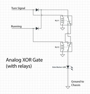
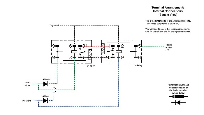
A circuit needs to be created which allows the side-markers to blink alternately to the turn signal with the headlights on, or with the turn signal when the headlights are off. This is done with an analog XOR (exclusive OR gate). The side-marker bulb circuit fix is thanks to a post by Apotropaic_Sphinx on the CherokeeXJ subreddit https://www.reddit.com/r/CherokeeXJ/...o_led_19972001. I followed his circuit and added the pin-outs for the relays that I selected.
I used components rated high enough that they can still be used with standard incandescent bulbs if someone replaces one of the LEDs in the future. The side-marker circuit has two 194 bulbs which use 0.27A each (incandescent rating) and much less with LEDs. Therefore, the circuit should be able to handle 0.55A or more. I have used 1A 12V micro-relays and 1A diodes.
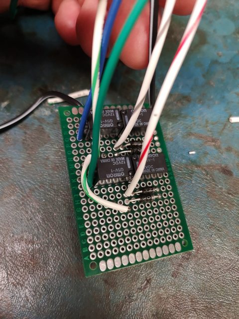
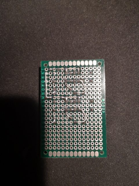
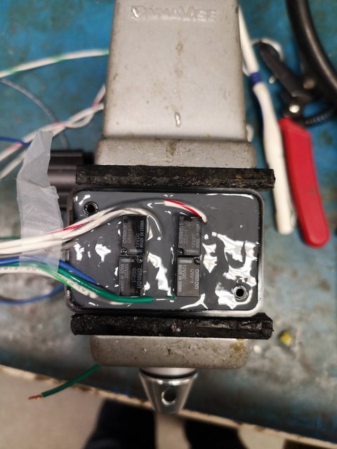
I assembled the circuit on a prototype board and soldered it up. After verifying the connections and testing with a bench power supply, I potted it into a small enclosure with some epoxy to make it waterproof.
Changes to the factory wiring:
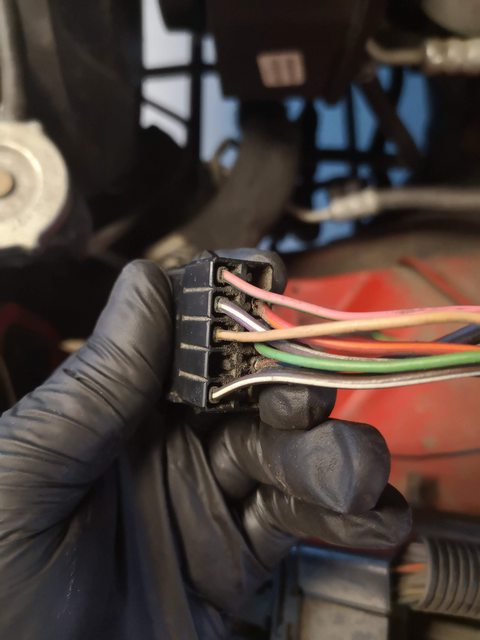
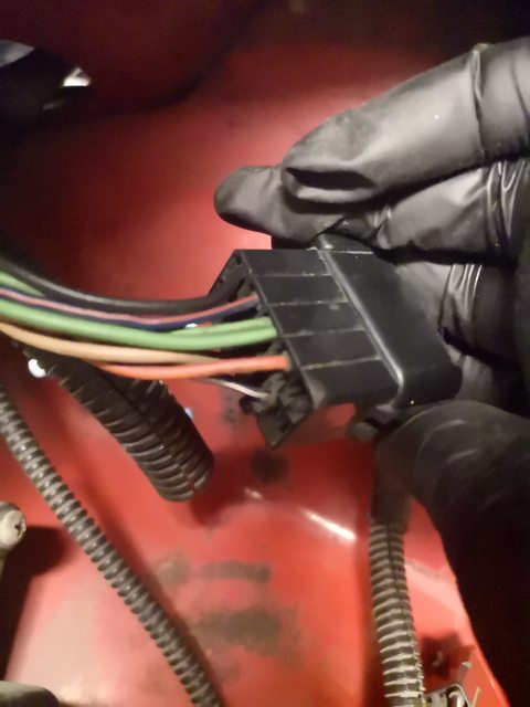
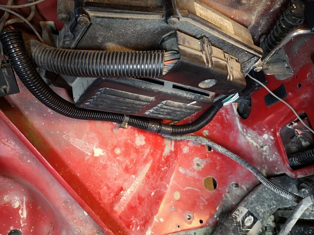
I had previously eliminated the C106 connector in the engine bay, which is located beside and below the PCM at the front drivers side. It was not a waterproof connector from factory and likely most XJs have some corrosion on these pins of varying degrees. These are all the wires for the side-markers, turn signals, and headlights. You can either replace the factory connector with something else, keep the factory connector or connect the wires directly together eliminating it. I chose the last option.
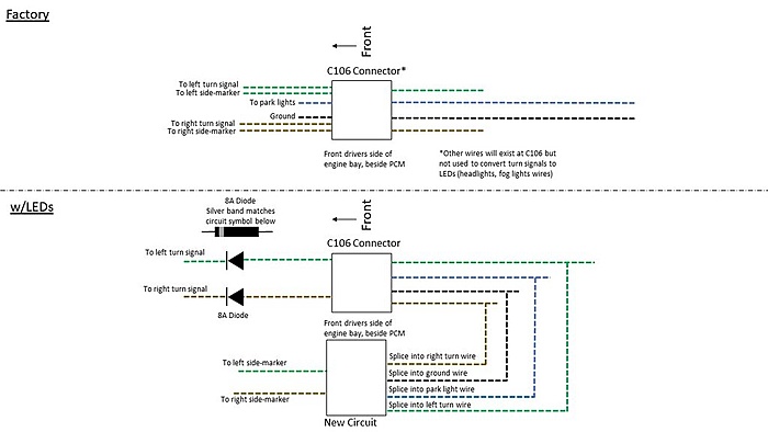
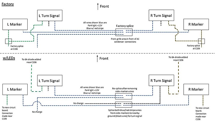
There are two green wires and two tan wires on one side of the connector, and only one of each on the other side. These are the feed wires for the turn signal and the side-markers. I cut my previous splice apart, and traced with a multimeter to find which wire goes to the side-markers and which one went to the turn signal. The wire going to the side-marker will be connected to the new circuit. Follow the following wiring diagram to splice in the new side-marker circuit and make the necessary changes. The circuit needs to be connected to the parking light, ground, and both L and R turn signals.
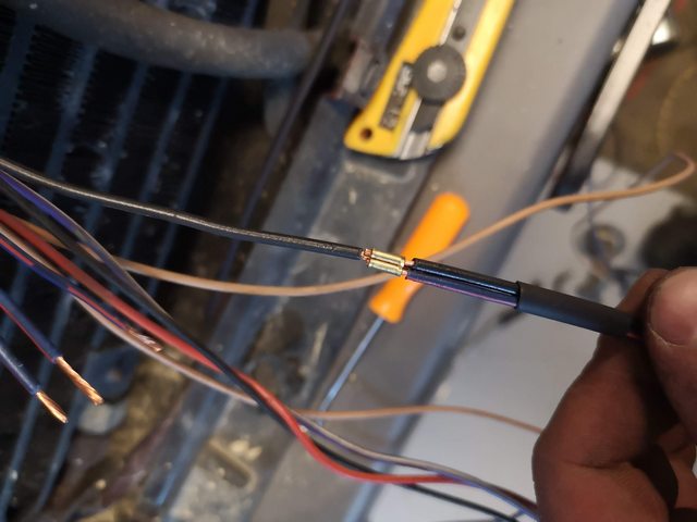
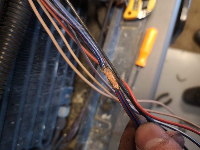
I spliced in my new circuit using Molex open barrel crimps with adhesive lined heat-shrink tubing, but you can use solder or other type of crimp connector. I prefer using crimps because the factory wires are a low strand count and hard to solder in any other preferred way besides a simple overlapping joint which may not be the best for long term vibration. You may find that corrosion has crept into the wires a long distance from the C106 connector.
The wiring at the side-markers needs to be changed so that the parking light wire becomes a ground instead of connecting to the factory location which is causing our issues. Follow the diagram below to make the necessary changes:
In order to keep this re-wire as neat as possible, I found the factory splice where all the parking light wires were tied together which is located on the passenger side, near where the A/C condenser connections are made. You can see the factory uses an ultrasonic weld to connect them which is the most common in automotive wiring and covers with adhesive lined heat shrink. Cut this splice apart and connect the parking light wires coming from the side-markers and splice them into the nearby black ground wire, following the diagram.
Replace all wires back into the factory heat shrink and tidy up with new split loom and electrical tape as needed. I mounted the circuit box with some Velcro.
Test out your new wiring job and enjoy brighter, instant-on and less current draw of LED lights!
The good news is that replacing the rest of the bulbs in the Jeep with LEDs is simple plug and play as they do not have the dual filament elements.
This writeup is LITERALLY incredible and I'm stunned that you took the time to do it, kstopp. This is EXACTLY the issue I've been having and it is so nice to know not only exactly what is causing it but how to fix it!!! Truly off the hook. So much other misinformation out there, including from retailers who should know better - thank you!!!
I believe I've now got everything I need to do this, but I've got two questions. First, in the diagram showing the two 5-pin relays (I'm using standard, blade-type auto relays since I am NOT smart enough to do the other), are the relays shown in a powered or unpowered state? Just can't figure out which should be 87 and which should be 87a, and I'm finding conflicting "answers" about whether the standard for wiring diagrams is to show them powered or not.
Second, I've got a winch mounted in a bumper in front of the grill, and I'd really like to avoid removing all that to get at that factory ground splice behind the grill - am I reading correctly that I could simply run the blue/red wire from each side marker directly to a nearby ground?
By the way, when putting the diodes in before the turn signals, I discovered that, at least on my 95, even though there are two green and two tan wires, the turn signal wire is larger gauge than the side marker wire, so hopefully that can help somebody else out.
Again, this writeup is just amazing - thank you so much!! Can't believe it hasn't gotten more love. It's amazing that someone understands the factory wiring enough to know how to fix it for LEDs - I have NEVER heard of an XOR gate but I sure am glad to know now.
I'm glad to hear it's useful to at least one other person! Makes the time investment worth it.
The diagrams are in the unpowered state. Here's a little bit of info I dug up on the common automotive 5-pin relays, you could also verify this by checking the resistance between pins 30 and 87A with the relay coil unpowered. It should be very low resistance ~0Ohms, usually referred to as NC or normally connected contact. Just incase you have an uncommon relay layout.
You are right about the factory splice, I just did that to make the wiring as neat as possible but it will work just the same if you run the wires to a nearby grounding point (or make one to the chassis).
Thanks so much for the response. Again, I can't believe there is ONLY this one resource on the entire internet (except for the Reddit thread) to address this issue - you know a whole lot of people have tried replacing their XJ bulbs with LEDs only to encounter the exact problems we did! Man, this is incredible. I got the diodes put in-line for the turn signals, now to assemble "the beast" - as I'm too stupid to mess with circuit boards, I'm putting all the relays, etc. into a comically-oversized enclosure from the hardware store. But - ought to work just the same! Once I get everything done and working I'll post back.
Kstopp, I NEVER doubted you or your method - but I certainly doubted my ability to execute it! I've never touched a circuit board. I went through several stages after finding your writeup: 1. Well that's my exact issue, but I can never do this. 2. Wait, he said it could be done with regular relays and diodes 3. I can possibly do this. That's the genius of this - you clearly have EXTENSIVE electrical/engineering knowledge, yet you wrote this up such that someone even like me could do it.
Now let's all agree - your install is a MILLION times cleaner than mine!!! I mean, why would you want that nice, clean, small circuit board/enclosure WHEN YOU COULD HAVE THIS UNHOLY MONSTROSITY TAKING UP 4/3 OF THE AVAILABLE SPACE IN THE ENGINE BAY
Yall would not BELIEVE how much crap is stuffed in there - it's actually too small an enclosure. There's four 5-pin auto relays in there, four blade-type diodes, and a bunch of wiring. But it all worked!! If anybody else wants to do this the idiot way, here's what I ordered:
I used butt-splice connections, and I don't have tremendous faith in them, but it was my only option outside of a wire nut, and I wasn't about to do that. My soldering gun gave it up last week, and of course I didn't get it taken care of. Oh well - ought to be a few years at least. And, as posted earlier, I simply grounded out each side marker locally rather than having to remove my winch/grill/etc.
Finished product!
It doesn't flash as fast as the first GIF, I just suck at making GIFs. Got an LED flasher so it flashes normal speed. Second GIF is accurate.
Kstopp, we all have reasons to think less of humanity because of the internet, but you sure are one of the good ones. You took so much time to write up a perfectly detailed and accurate explanation of how to get around a pretty glaring issue, and this total stranger sure appreciates it. I'll probably never shake your hand, but I'd like to as I buy you a beer. Thanks for making this world a better place!
That's fantastic, thanks for posting back with the result! I'm glad you stumbled upon the write up and stuck through it to get it done! Great looking XJ you have
If I replace all the exterior lighting with LEDs except for the front side maker lights, will I still have issues with the lighting? It seems most people have reported issues when they have replaced every incandescent with LEDs.