
1987 Wagoneer Limited

Thread Starter
Seasoned Member
Joined: Jan 2011
Posts: 303
Likes: 4
From: Austin
Year: 1987
Model: Wagoneer
Engine: 4.0
Did this a few weeks ago, just getting around to posting it.
26May12
Fuel Pump
Had some intermittent hesitations and a couple stalls, so it was time to replace the fuel pump.
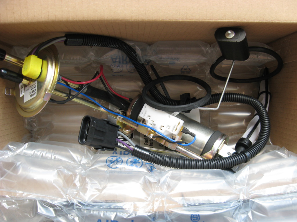
Without reading the reviews, I went to vatozone and picked up the Airtex pump and sender unit.
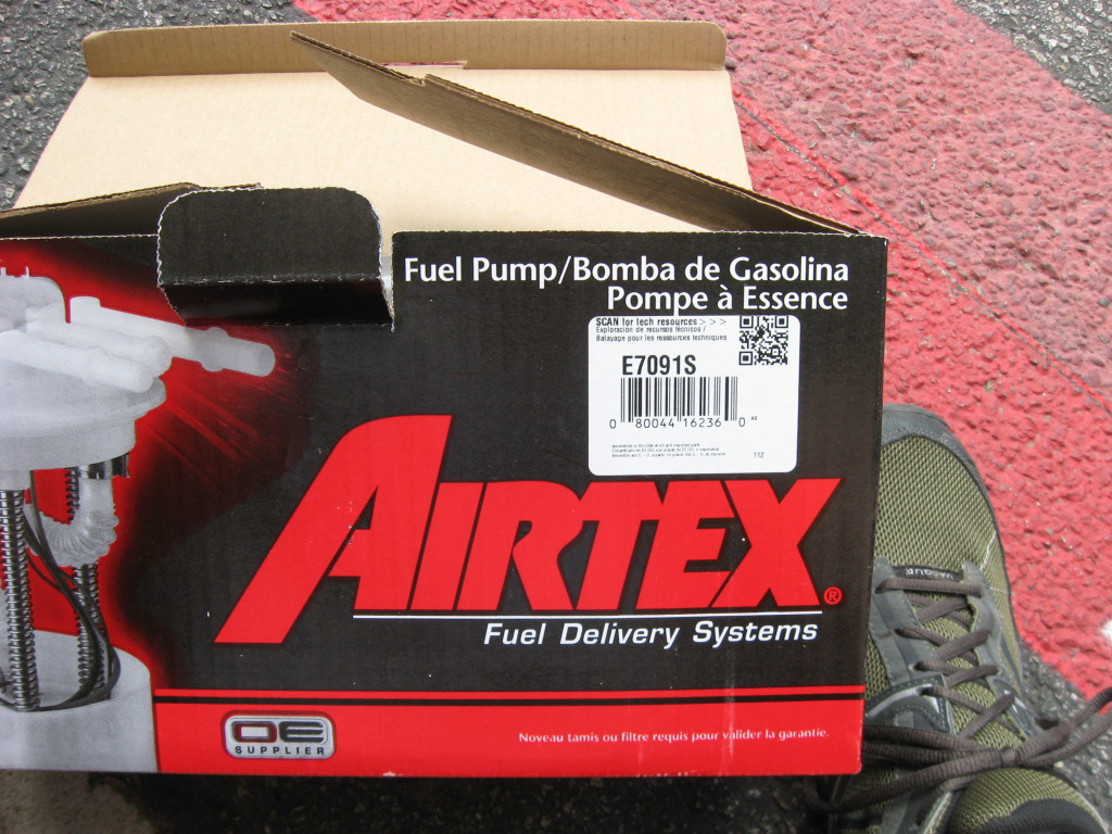
Looks nice and pretty; even comes with two different o-rings.
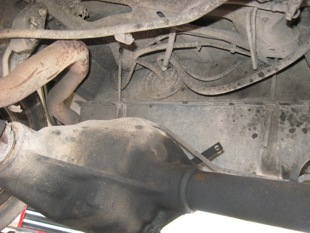
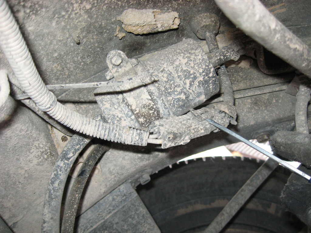
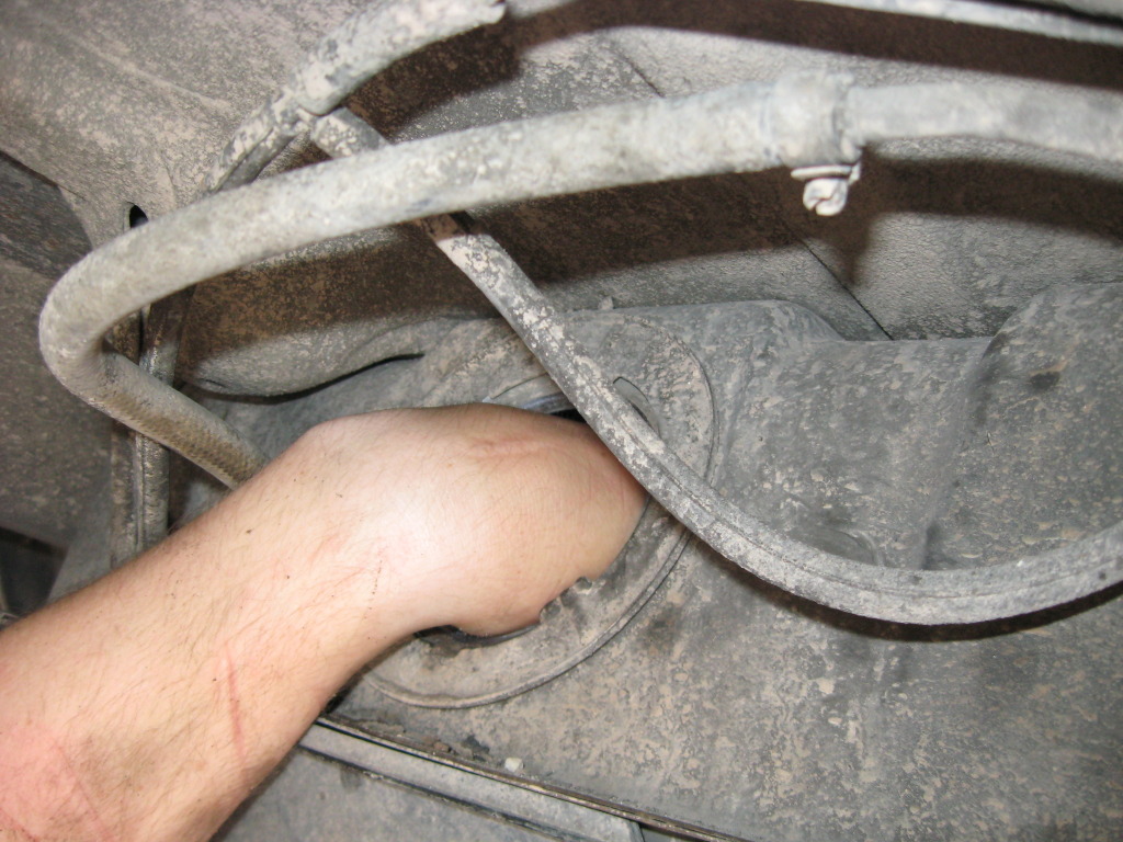
Disconnected the battery, relieved the fuel pressure via the fuel rail, took off the filler cap for the tank, and jacked the rear end up.
Disconnect the hoses (label them if you want - I didn't) and disconnect the wires coming out of the pump.
Throughout this process, I got doused in the face repeatedly with fuel....I'm sure there was a better way to control the hoses, I was just in a hurry.
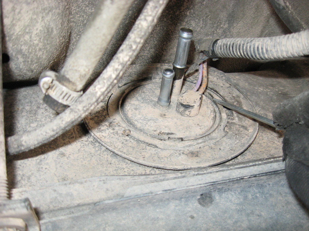
Rotate the locking ring counter clockwise and remove.
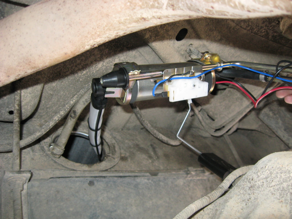
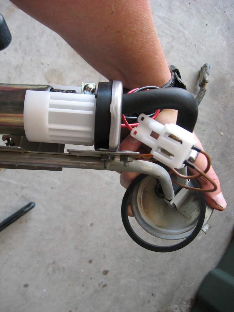
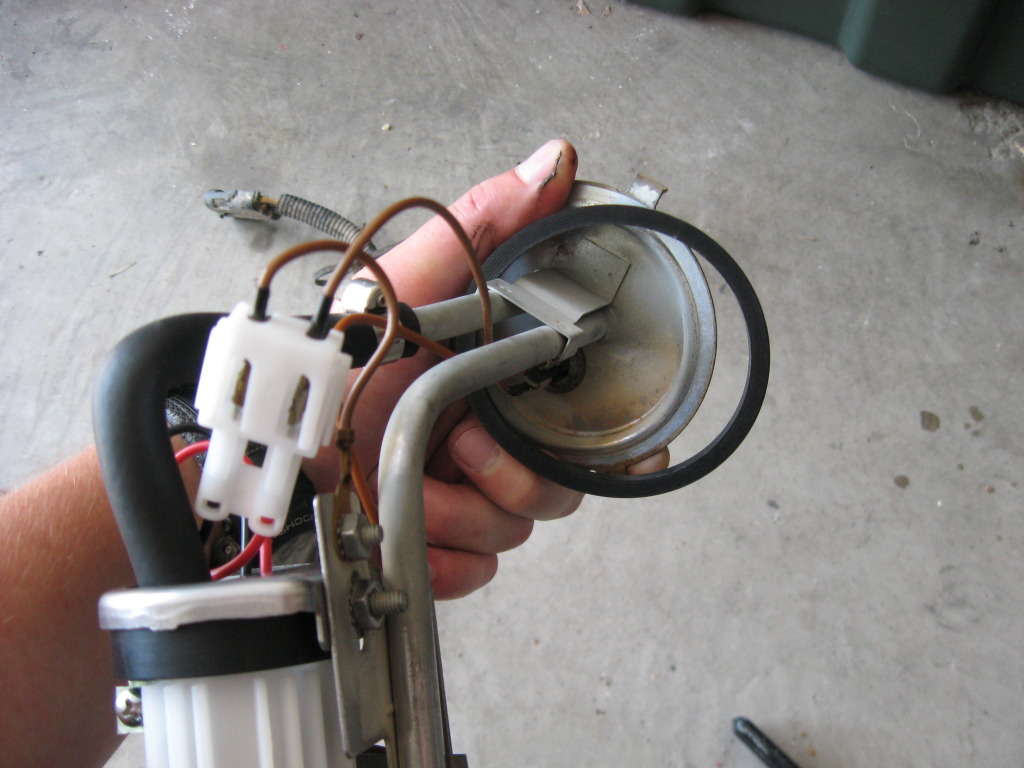
Carefully pull the sending unit/pump assembly out of the tank. Fuel will leak out of those tubes as you rotate it, so be careful.
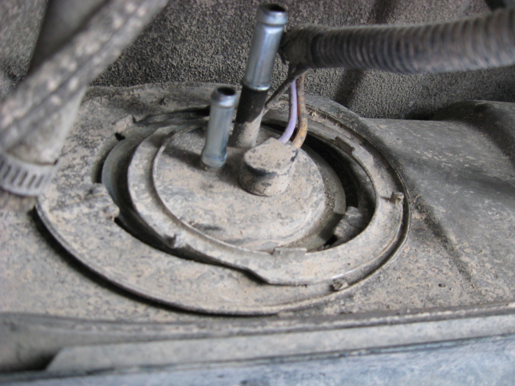
If it didn't come out with the unit, fish around the tank and pull out the rubber centering cone.
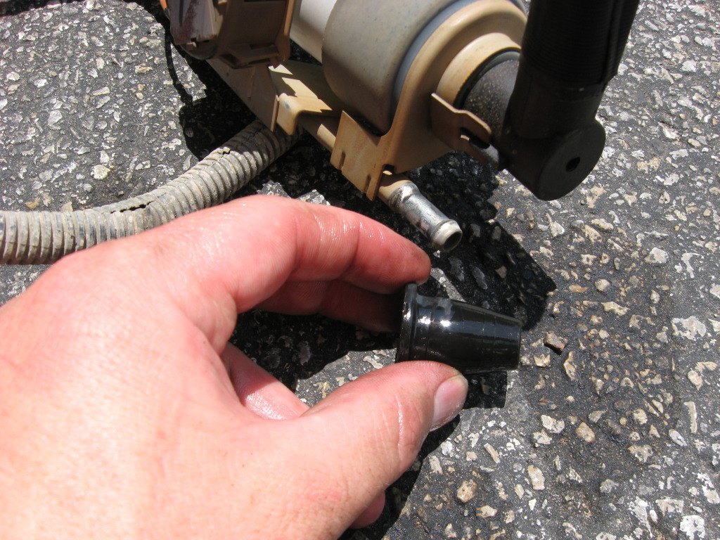
While you're in there, get an idea of what the inside looks like and where that new pump will have to set.
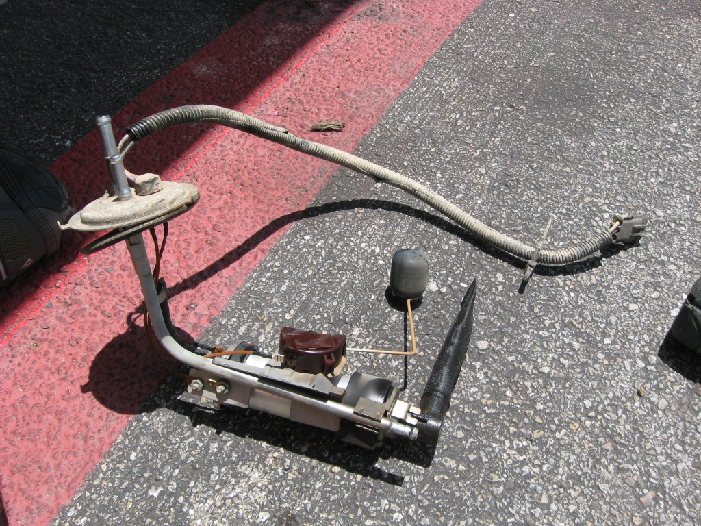
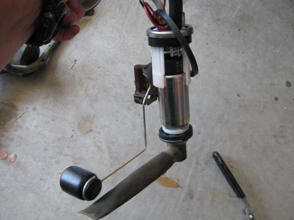
Long story short, I installed the Airwix
Then went and filled up.....and watched $20 worth of gas promptly spill out of the tank, as the new sending unit didn't seal properly. Got it home, switched out the o-ring, and the same thing happened.....out she came and back to vatozone for a full refund.
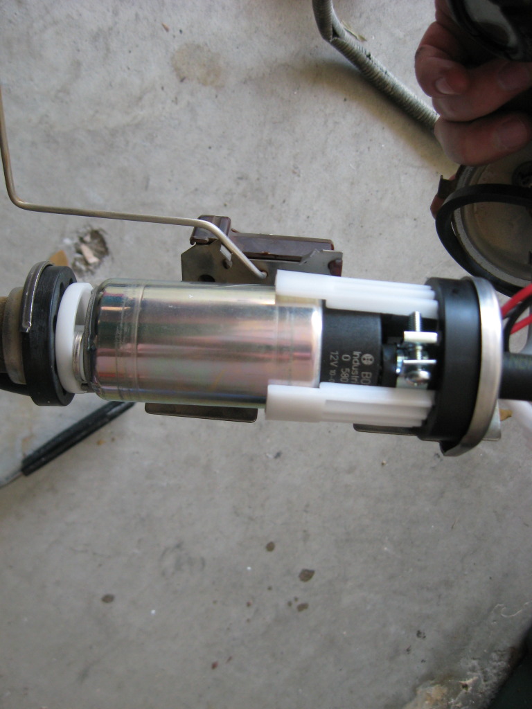
3 hours later, I located a Bosch 69302 pump from CarQuest.
It took a little to figure out the adapter (hope I did it right...haven't caught on fire yet...), but I put the new pump in the old sending unit and back it went into the tank....good as new
26May12
Fuel Pump
Had some intermittent hesitations and a couple stalls, so it was time to replace the fuel pump.
Without reading the reviews, I went to vatozone and picked up the Airtex pump and sender unit.
Looks nice and pretty; even comes with two different o-rings.
Disconnected the battery, relieved the fuel pressure via the fuel rail, took off the filler cap for the tank, and jacked the rear end up.
Disconnect the hoses (label them if you want - I didn't) and disconnect the wires coming out of the pump.
Throughout this process, I got doused in the face repeatedly with fuel....I'm sure there was a better way to control the hoses, I was just in a hurry.
Rotate the locking ring counter clockwise and remove.
Carefully pull the sending unit/pump assembly out of the tank. Fuel will leak out of those tubes as you rotate it, so be careful.
If it didn't come out with the unit, fish around the tank and pull out the rubber centering cone.
While you're in there, get an idea of what the inside looks like and where that new pump will have to set.
Long story short, I installed the Airwix
Then went and filled up.....and watched $20 worth of gas promptly spill out of the tank, as the new sending unit didn't seal properly. Got it home, switched out the o-ring, and the same thing happened.....out she came and back to vatozone for a full refund.
3 hours later, I located a Bosch 69302 pump from CarQuest.
It took a little to figure out the adapter (hope I did it right...haven't caught on fire yet...), but I put the new pump in the old sending unit and back it went into the tank....good as new
Thread Starter
Seasoned Member
Joined: Jan 2011
Posts: 303
Likes: 4
From: Austin
Year: 1987
Model: Wagoneer
Engine: 4.0
The old c101 connector clean-up...
Before:
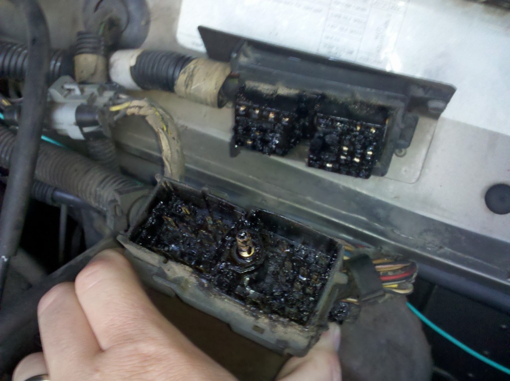
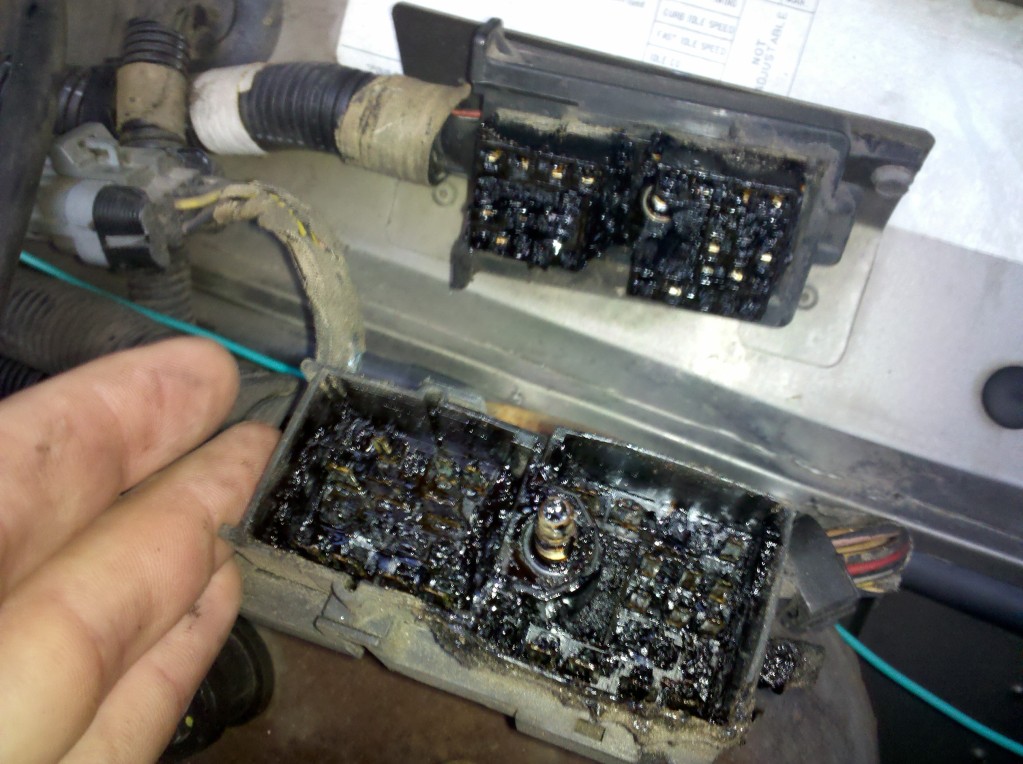
Some electrical parts cleaner, q-tips, and a small screwdriver later, a clean connector
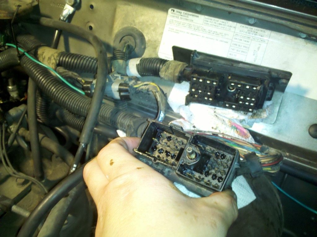
Put some dielectric grease in there and screwed it back together.
Now to see if my flaky ground is gone....
Before:
Some electrical parts cleaner, q-tips, and a small screwdriver later, a clean connector
Put some dielectric grease in there and screwed it back together.
Now to see if my flaky ground is gone....
Thread Starter
Seasoned Member
Joined: Jan 2011
Posts: 303
Likes: 4
From: Austin
Year: 1987
Model: Wagoneer
Engine: 4.0
7/1/12
203,956
My power locks haven't worked since before I got it. You hit the button and it looks like it's trying, but nothing would happen. Stumbled across this writeup by Greg Smith over on NAXJA and thought I'd give it a shot.
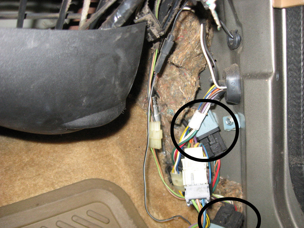
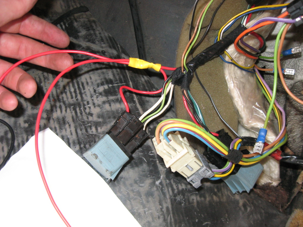
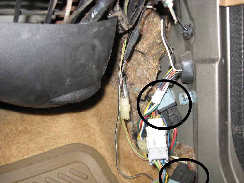
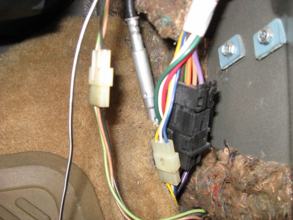
It took me almost an hour to figure out that my XJ originally came with keyless entry and these two relays were part of that factory system. The light green and tan wires you need are on the XJ side (not the door side) of the black connector.

I cut them about 4" back from the connector. If I had to to it again, I'd cut them closer to the connector, so the relays don't sit under the carpet.
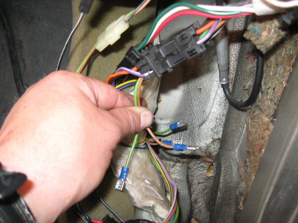
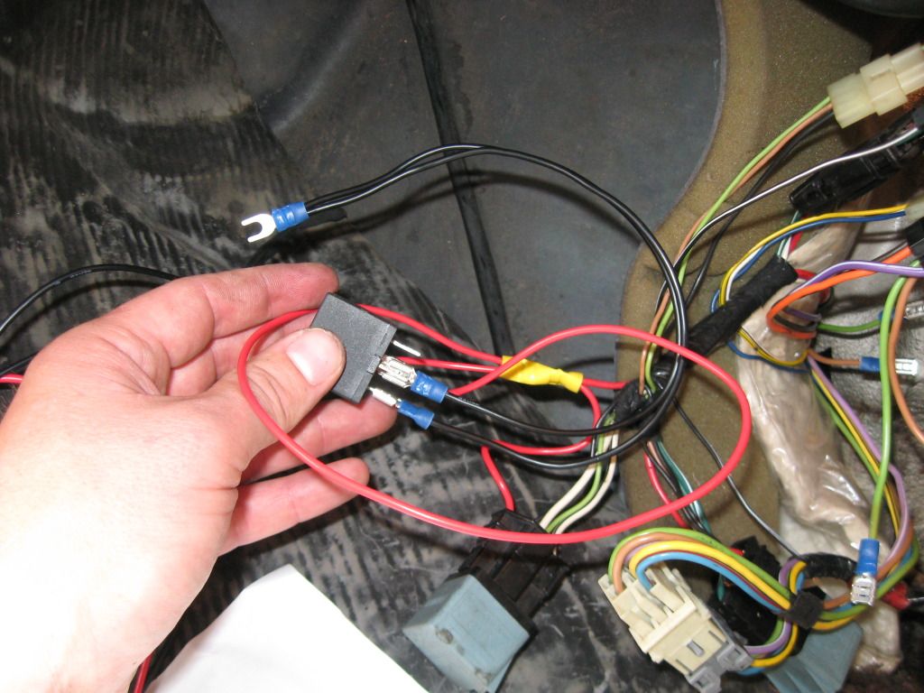
Instead of running power directly from the battery/starter terminal like the write up suggested, I spliced into the high side of the power going to the keyless entry relays. There was good voltage there (13.1VDC) and thought that'd be easier.
Next, the grounds. I removed the broken tabs from the original relays and used one of the bolts as my body ground. Plug 'em all up...

Lay them in and tape up the terminals.
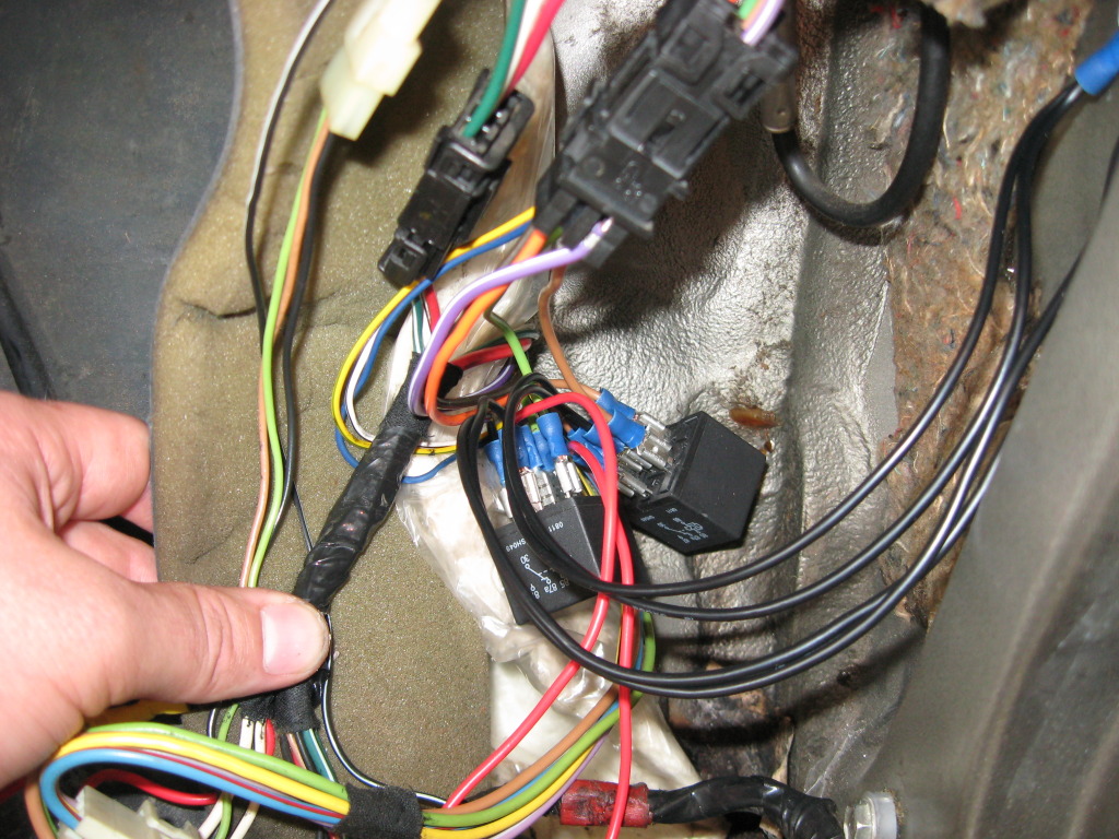
Like I said, I'd prefer if they were behind the kick panel as opposed to sitting under the carpet, but none the less, now all 5 locks give a solid "THUNK" when you hit the lock/unlock button!
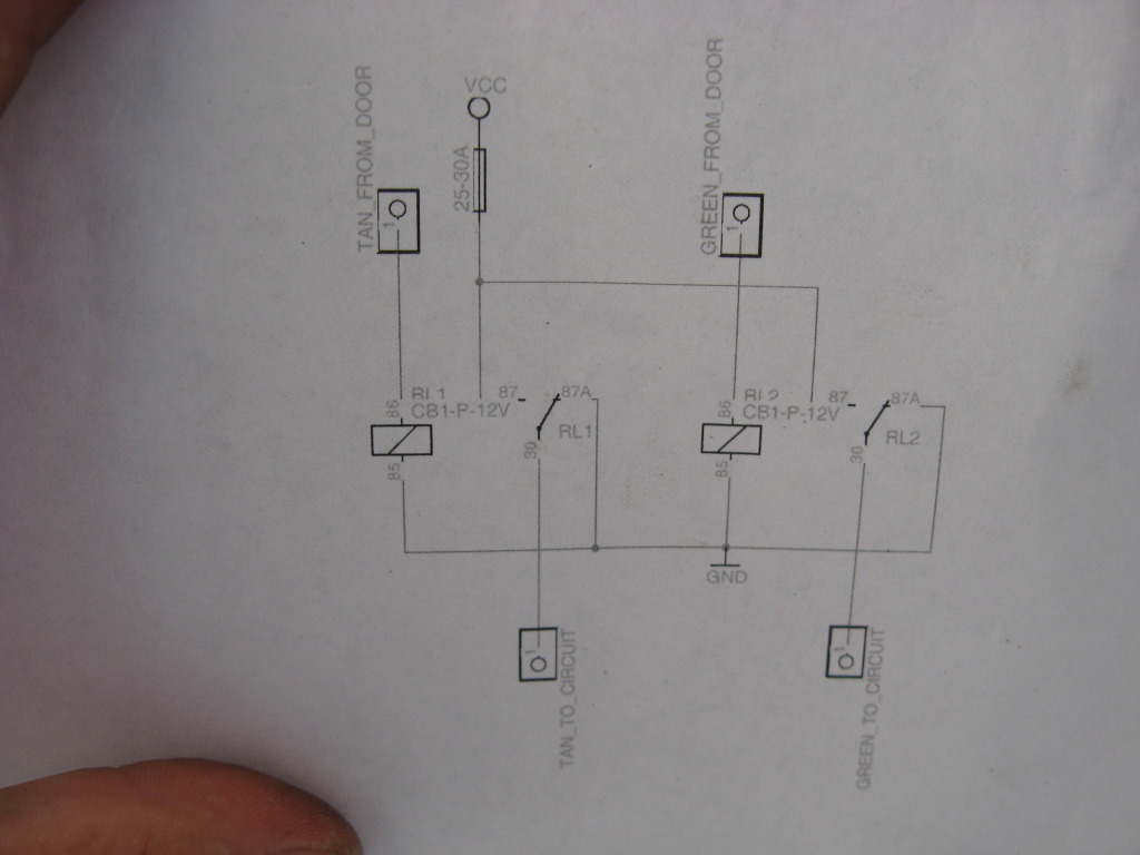
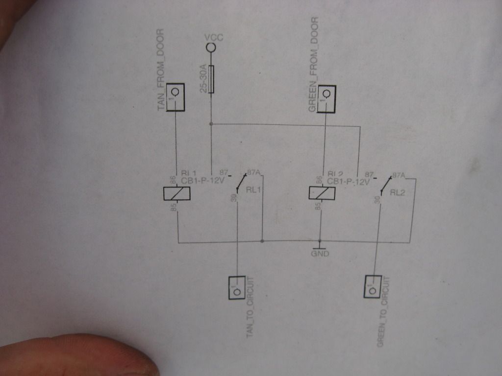
If the description of the wiring was confusing, here's a schematic and a link:
http://www.jeeptuning-foto.com/album...two-relays.pdf
203,956
My power locks haven't worked since before I got it. You hit the button and it looks like it's trying, but nothing would happen. Stumbled across this writeup by Greg Smith over on NAXJA and thought I'd give it a shot.
Power Door Lock Fix for Reluctant Locks on Pre 1991 Jeep Cherokees
(for post 90 models with a similar problem I woud check the relays in the passenger side kick
panel)
The Problem:
Some (usually not all) of the power door locks stop working, or more commonly work
inconsistently on the lock and/or unlock position. The problem usually starts when the Jeep gets
older and the locks become stiffer. Cold weather seems to cause the most problems. The rear
hatch and rear doors seem to the most troublesome since they are on the end of the circuit and
experience the largest voltage drop.
The Cause:
The cause is a design flaw which causes a loss of 2 volts. As the Jeep gets older and the locks
become stiffer and the connections develop some resistance the amount of voltage that gets
through the system is no longer enough to work the power locks near the end of the circuit. With
the pre 1991 wiring all the power for the power door locks passes through the passenger door
lock switch regardless of whether you trigger that switch, the driver’s side door switch or the
remote keyless opener (if you have it). Power leaves that switch going to the door locks through
the tan wire for unlock and the light green wire for lock.
The power goes from the passenger door switch to a splice in that door for the power lock in that
door and then goes out the door and into the kick panel in front of the door on the passenger side.
By the time the power gets to the kick panel it has lost about 2 volts. I replaced my passenger side
switch suspecting a bad switch but still lost 2 volts out of the switch. I then did a full continuity and
resistance test on the switch per the factory service manual and found no problems. I have never
figured out why this happens but apparently Jeep could not either since they changed the wiring
starting in 1991 to compensate for this problem. (Note the wiring change can be done like the post
1990 models but the fix I provide below is a lot easier in my opinion.) After the now lower voltage
gets to the passenger side kick panel it goes under the carpet and over to the driver’s side and
hits a master splice under the front floor carpet for the wires going to the driver’s side front and
rear doors and the passenger side rear door. I unwrapped the tape around the splices and
checked all the splices and they were clean and tight. Then I measured the voltage at the
remaining power locks. By the time the voltage gets through the master splice is loses another 2+
volts and is not enough to power the locks consistently when they become stiff from old age or
cold weather.
The Fix/Repair:
First make sure you are getting around 12 volts of power to your passenger side door switch
directly or when you trigger the lock or unlock switch from the driver’s side or by the remote. You
can test the voltage with a multi-meter at the wire harness connector in the passenger-side kick
panel where the dark green, white and red wires go into the front door.
Assuming you have a full voltage supply to the passenger side switch, the fix is to install two
relays in the passenger-side kick panel on the lock and unlock wires coming from the passenger
side switch. The relays will increase voltage back up to 12 volts to compensate for the loss
caused by the passenger side switch. With the voltage increase provided by the relays, the
voltage at the remaining power door locks is increased by approximately 2 volts, enough to power
all the locks, even in cold weather. This of course assumes that no wiring problems exist from the
splices to the door locks. If you still have a problem at a particular door lock measure the voltage
and make sure it is over 9 volts. With my fix it should be closer to 10 and perhaps 9 at the rear
hatch.
The relays to use are 5 blade, 12 volt, 30 amp minimum rated relays with blades marked 85, 86,
87, 87a and 30. These relays are the same as those used for the keyless remote relays found in
the passenger-side kick panel so you may find them cheap at the bone yard. You can also find
them in automotive electric supply stores. Look in the section that has lighting upgrade supplies.
For an easier install it is also best to buy wiring sockets that fit the relays. Here is a link to
partsexpress.com an online supplier that has relays and sockets at reasonable prices. I used 2
bosch relays # 330-070 and 2 sockets # 330-075 (although 1 dual socket 330-078 could be used I
believe). http://www.partsexpress.com/webpage....oup_ID=31&SO=2
Here is how I did the wiring: I used the two 12v relays. They have 5 blades: 86 is trigger pwr from
the passenger dr switch; 85 is ground; 87 is the new pwr source; 30 is the path to the lock and
87a is to ground (in this application). I cut the Lgreen and tan wire about 5 inches forward (toward
the front of the Jeep) of the wire harness connector that connects the wires to the wires coming
out of the passenger frnt dr. In this example I attached the tan unlock wire coming from the
passenger frnt door to 86 and 85 to ground; 30 is attached to the tan wire going to the door locks;
and 87a is to ground. I used the new 10 gauge pwr line I had previously run to the battery/starter
relay post with a 30 amp inline fuse. You can take off pwr from a splice on the red pwr going into
the passenger door instead. (The same approach is used for the lgreen wire using the other new
relay for for the lock circuit.) The key to making this work was 87a to ground. When the lgreen or
tan wire are not in pwr mode they provide ground path to ground through the driver’s side switch.
With my new relays I substituted a new body ground instead. As a result I increased voltage and
created new better grounds. The locks now all slam open and closed even in very cold weather.
Hope this helps. At least 30 people I have heard from have done this mod with great success.
Greg
I pulled my kick panel off and was thrown for a loop when I saw these two relays. They looked like this mod had already been done:(for post 90 models with a similar problem I woud check the relays in the passenger side kick
panel)
The Problem:
Some (usually not all) of the power door locks stop working, or more commonly work
inconsistently on the lock and/or unlock position. The problem usually starts when the Jeep gets
older and the locks become stiffer. Cold weather seems to cause the most problems. The rear
hatch and rear doors seem to the most troublesome since they are on the end of the circuit and
experience the largest voltage drop.
The Cause:
The cause is a design flaw which causes a loss of 2 volts. As the Jeep gets older and the locks
become stiffer and the connections develop some resistance the amount of voltage that gets
through the system is no longer enough to work the power locks near the end of the circuit. With
the pre 1991 wiring all the power for the power door locks passes through the passenger door
lock switch regardless of whether you trigger that switch, the driver’s side door switch or the
remote keyless opener (if you have it). Power leaves that switch going to the door locks through
the tan wire for unlock and the light green wire for lock.
The power goes from the passenger door switch to a splice in that door for the power lock in that
door and then goes out the door and into the kick panel in front of the door on the passenger side.
By the time the power gets to the kick panel it has lost about 2 volts. I replaced my passenger side
switch suspecting a bad switch but still lost 2 volts out of the switch. I then did a full continuity and
resistance test on the switch per the factory service manual and found no problems. I have never
figured out why this happens but apparently Jeep could not either since they changed the wiring
starting in 1991 to compensate for this problem. (Note the wiring change can be done like the post
1990 models but the fix I provide below is a lot easier in my opinion.) After the now lower voltage
gets to the passenger side kick panel it goes under the carpet and over to the driver’s side and
hits a master splice under the front floor carpet for the wires going to the driver’s side front and
rear doors and the passenger side rear door. I unwrapped the tape around the splices and
checked all the splices and they were clean and tight. Then I measured the voltage at the
remaining power locks. By the time the voltage gets through the master splice is loses another 2+
volts and is not enough to power the locks consistently when they become stiff from old age or
cold weather.
The Fix/Repair:
First make sure you are getting around 12 volts of power to your passenger side door switch
directly or when you trigger the lock or unlock switch from the driver’s side or by the remote. You
can test the voltage with a multi-meter at the wire harness connector in the passenger-side kick
panel where the dark green, white and red wires go into the front door.
Assuming you have a full voltage supply to the passenger side switch, the fix is to install two
relays in the passenger-side kick panel on the lock and unlock wires coming from the passenger
side switch. The relays will increase voltage back up to 12 volts to compensate for the loss
caused by the passenger side switch. With the voltage increase provided by the relays, the
voltage at the remaining power door locks is increased by approximately 2 volts, enough to power
all the locks, even in cold weather. This of course assumes that no wiring problems exist from the
splices to the door locks. If you still have a problem at a particular door lock measure the voltage
and make sure it is over 9 volts. With my fix it should be closer to 10 and perhaps 9 at the rear
hatch.
The relays to use are 5 blade, 12 volt, 30 amp minimum rated relays with blades marked 85, 86,
87, 87a and 30. These relays are the same as those used for the keyless remote relays found in
the passenger-side kick panel so you may find them cheap at the bone yard. You can also find
them in automotive electric supply stores. Look in the section that has lighting upgrade supplies.
For an easier install it is also best to buy wiring sockets that fit the relays. Here is a link to
partsexpress.com an online supplier that has relays and sockets at reasonable prices. I used 2
bosch relays # 330-070 and 2 sockets # 330-075 (although 1 dual socket 330-078 could be used I
believe). http://www.partsexpress.com/webpage....oup_ID=31&SO=2
Here is how I did the wiring: I used the two 12v relays. They have 5 blades: 86 is trigger pwr from
the passenger dr switch; 85 is ground; 87 is the new pwr source; 30 is the path to the lock and
87a is to ground (in this application). I cut the Lgreen and tan wire about 5 inches forward (toward
the front of the Jeep) of the wire harness connector that connects the wires to the wires coming
out of the passenger frnt dr. In this example I attached the tan unlock wire coming from the
passenger frnt door to 86 and 85 to ground; 30 is attached to the tan wire going to the door locks;
and 87a is to ground. I used the new 10 gauge pwr line I had previously run to the battery/starter
relay post with a 30 amp inline fuse. You can take off pwr from a splice on the red pwr going into
the passenger door instead. (The same approach is used for the lgreen wire using the other new
relay for for the lock circuit.) The key to making this work was 87a to ground. When the lgreen or
tan wire are not in pwr mode they provide ground path to ground through the driver’s side switch.
With my new relays I substituted a new body ground instead. As a result I increased voltage and
created new better grounds. The locks now all slam open and closed even in very cold weather.
Hope this helps. At least 30 people I have heard from have done this mod with great success.
Greg
It took me almost an hour to figure out that my XJ originally came with keyless entry and these two relays were part of that factory system. The light green and tan wires you need are on the XJ side (not the door side) of the black connector.
I cut them about 4" back from the connector. If I had to to it again, I'd cut them closer to the connector, so the relays don't sit under the carpet.
Instead of running power directly from the battery/starter terminal like the write up suggested, I spliced into the high side of the power going to the keyless entry relays. There was good voltage there (13.1VDC) and thought that'd be easier.
Next, the grounds. I removed the broken tabs from the original relays and used one of the bolts as my body ground. Plug 'em all up...
Lay them in and tape up the terminals.
Like I said, I'd prefer if they were behind the kick panel as opposed to sitting under the carpet, but none the less, now all 5 locks give a solid "THUNK" when you hit the lock/unlock button!
If the description of the wiring was confusing, here's a schematic and a link:
http://www.jeeptuning-foto.com/album...two-relays.pdf
 LOL
LOL
Thread Starter
Seasoned Member
Joined: Jan 2011
Posts: 303
Likes: 4
From: Austin
Year: 1987
Model: Wagoneer
Engine: 4.0
Originally Posted by lvcherokee
I will never be able to go in to that parts store again without a smile on my face!!
Thread Starter
Seasoned Member
Joined: Jan 2011
Posts: 303
Likes: 4
From: Austin
Year: 1987
Model: Wagoneer
Engine: 4.0
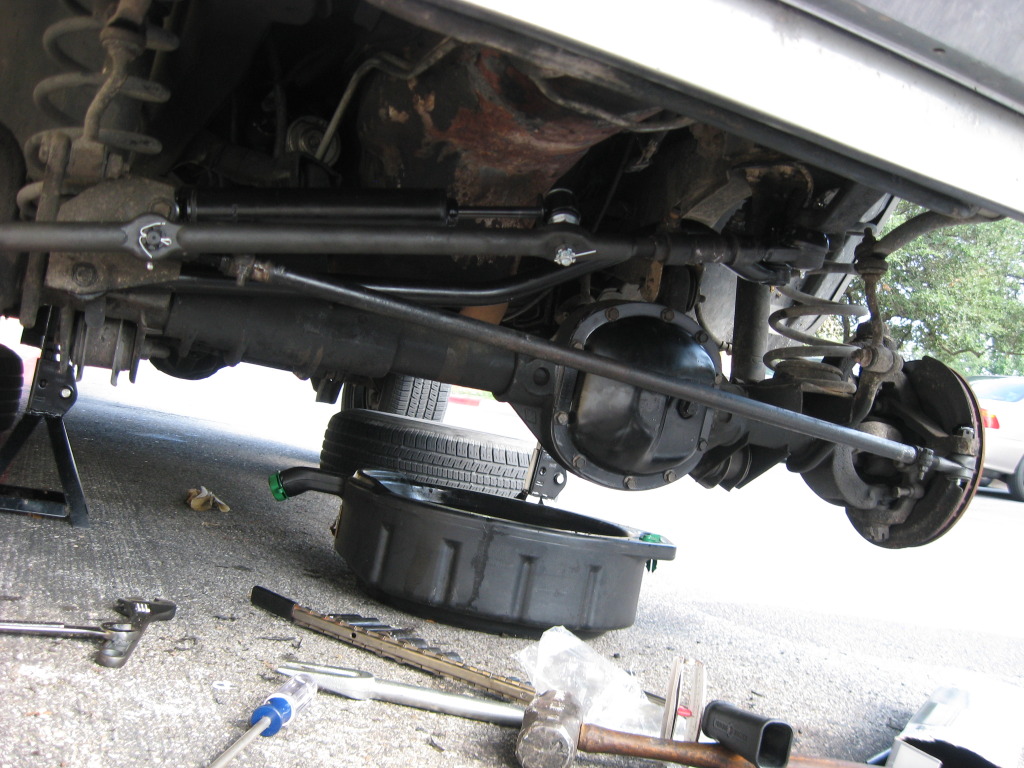
Cured my death wobble 
Spent 10hrs under the Waggy on the 4th doing diff fluid, TREs, and track bar.
Note: Before taking your diff covers off, be sure you can remove the fill hole plugs....nothing worse than draining all your fluid and not being able to refill it...
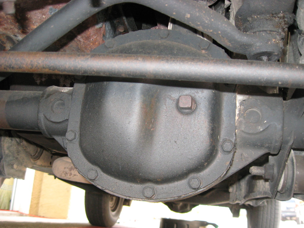
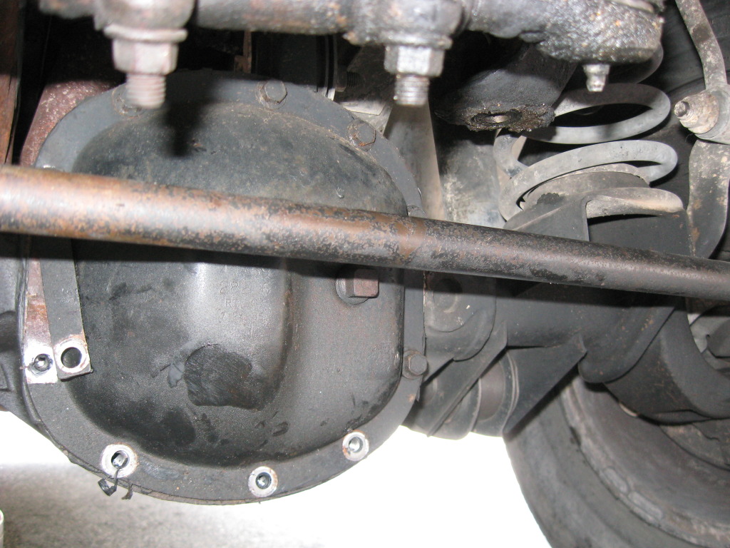
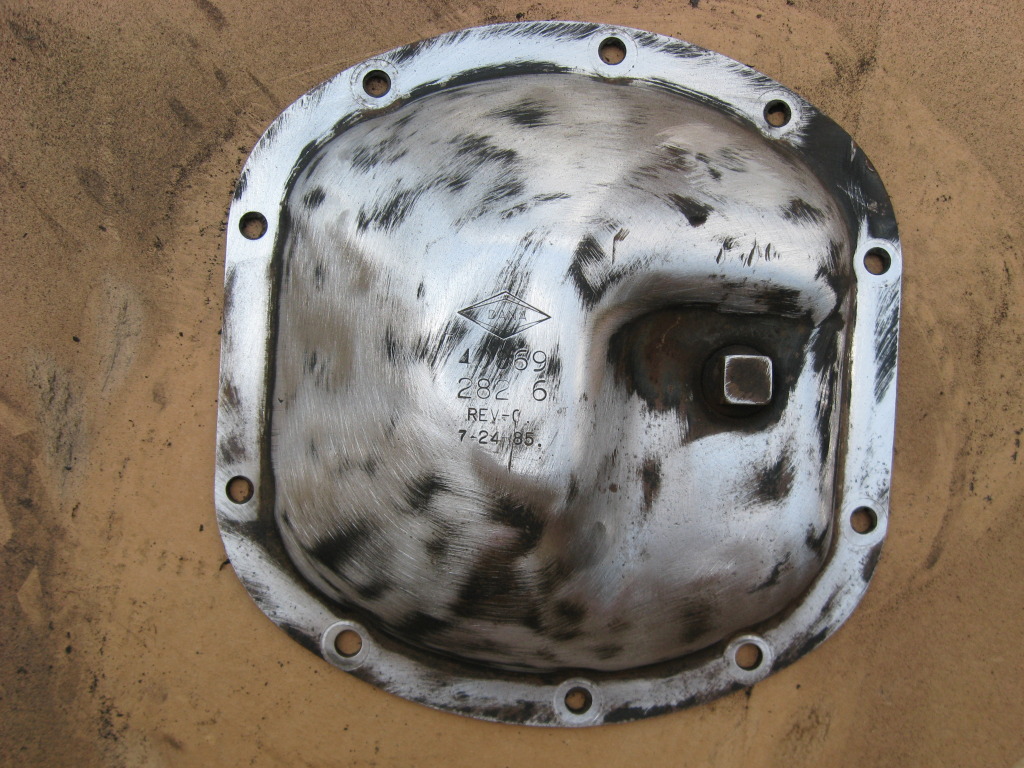
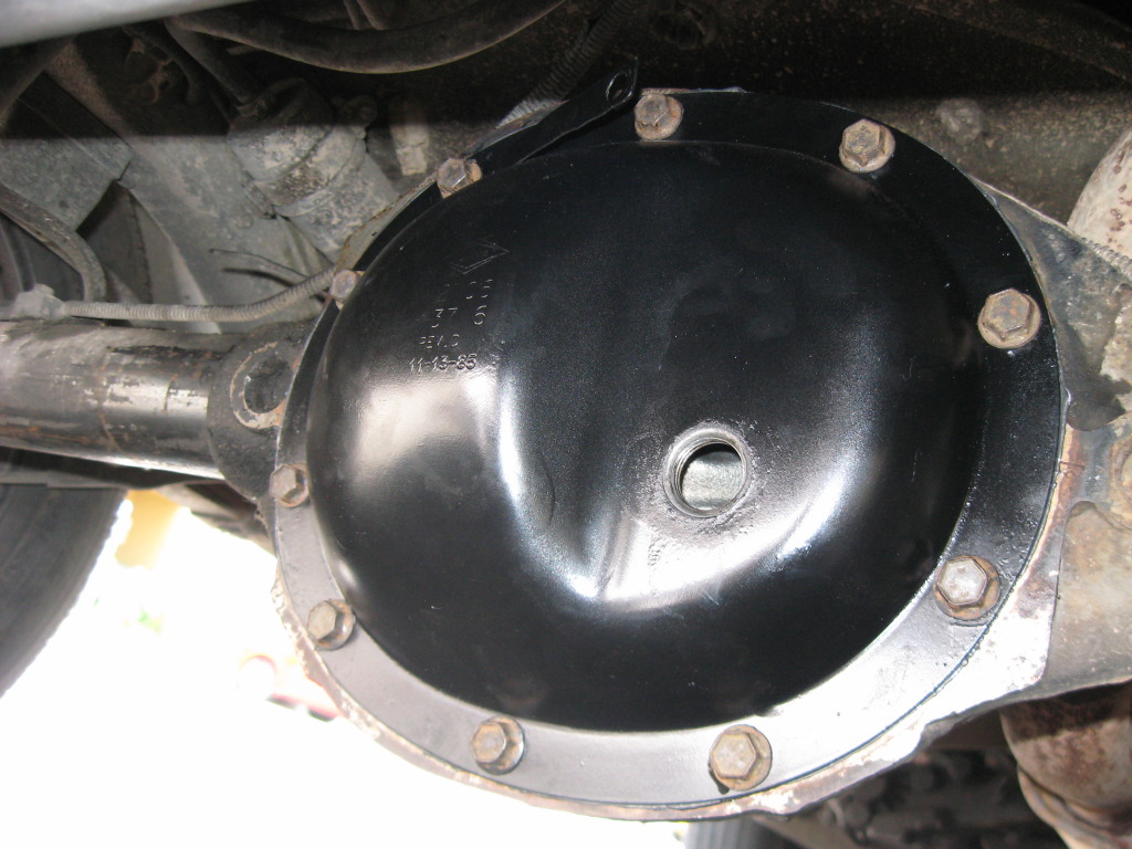
Rear diff had a little leak, nothing bad.
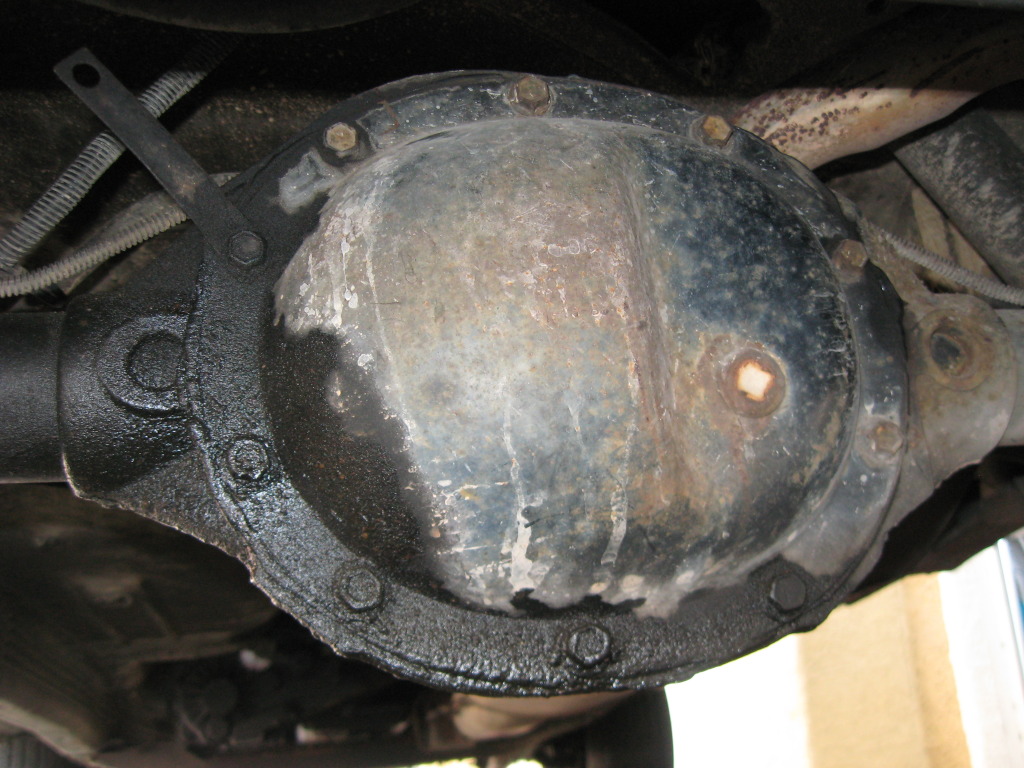
Take all the bolts but the top one out -leave it in but loose.
Putty knife to create some space.
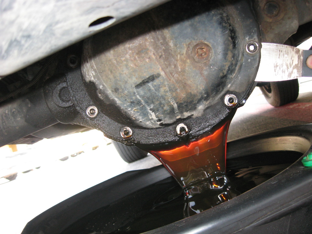
I have no idea the last time it was changed.
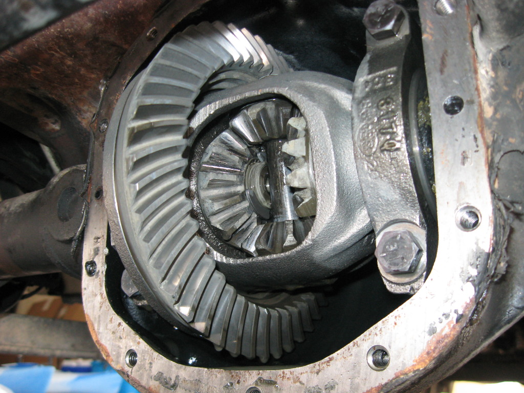
Inside the cover....nice little "water line"
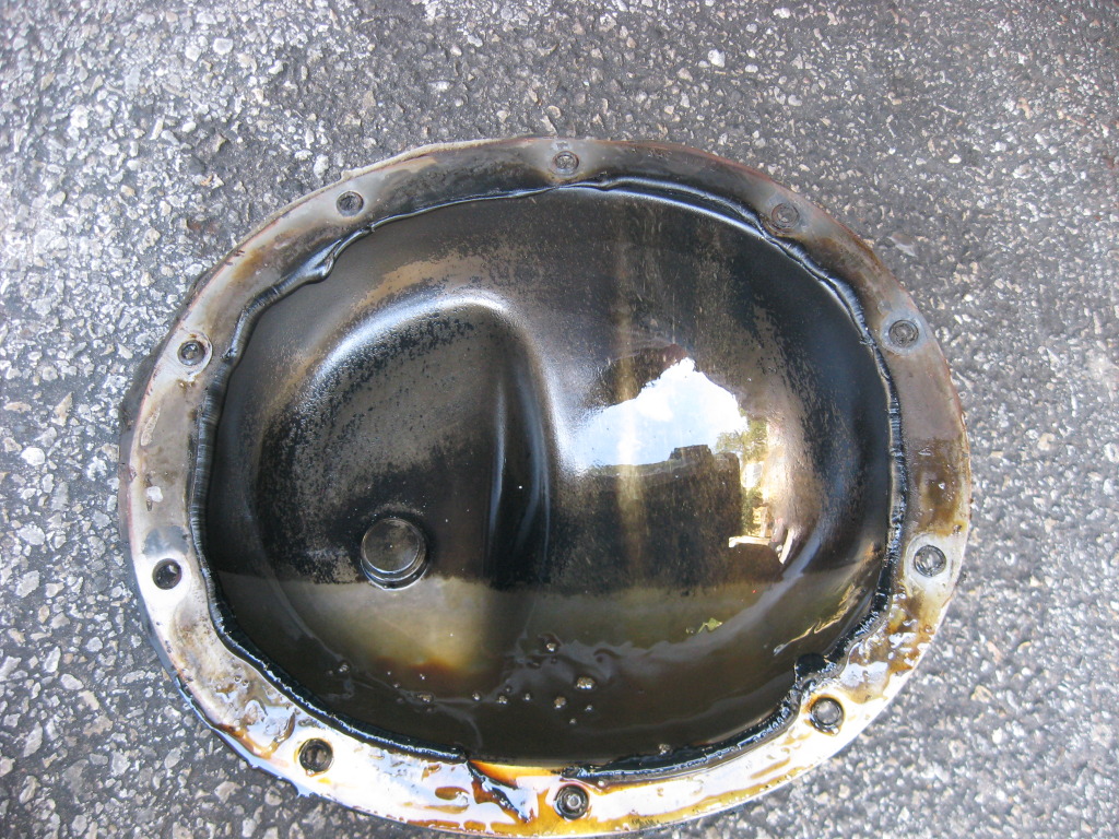
Teeth looked alright.
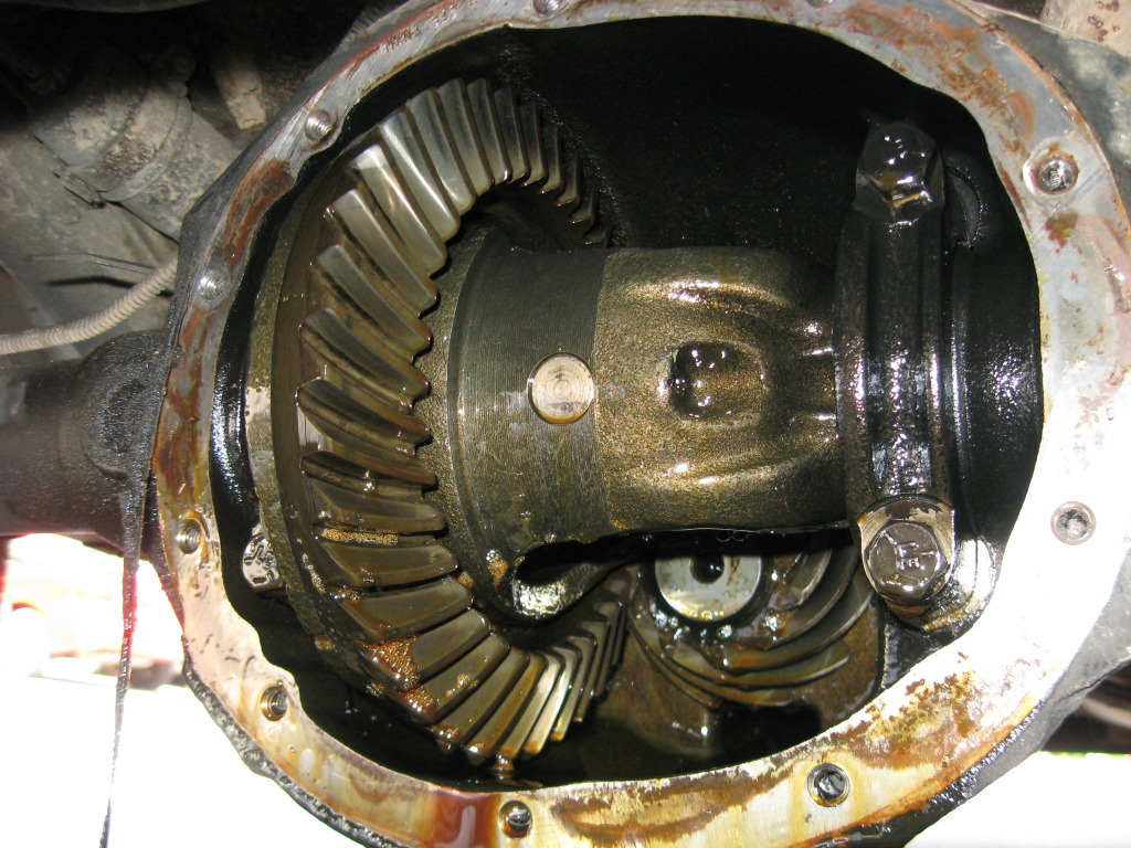
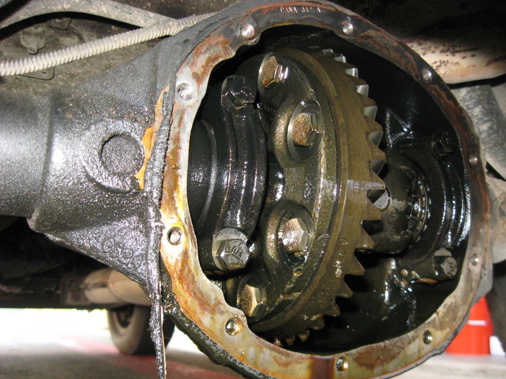
Used a can of brake cleaner and sprayed the crap out of the inside and outside.
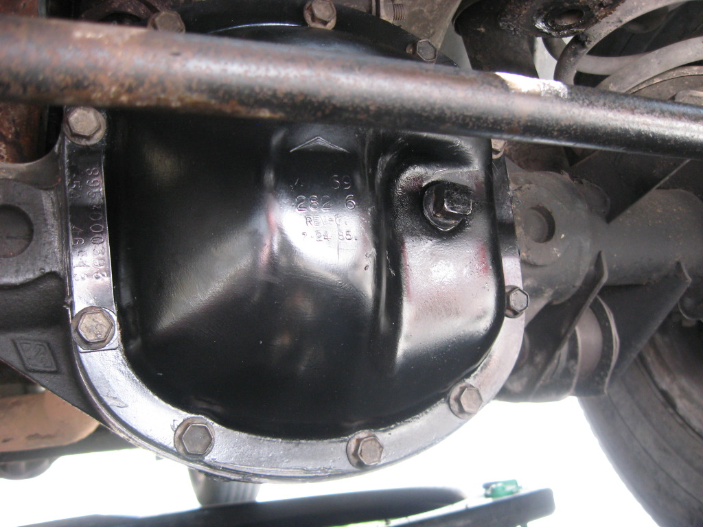
Set the cover aside and started on the front.
Got most of the bolts out, but that stupid track bar blocked two of them....maybe I wasn't trying hard enough, but I was going to be replacing it anyway, so off it came!
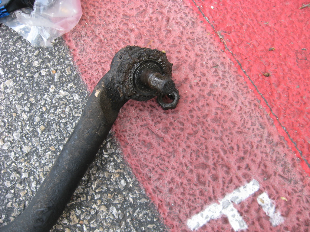
Pretty quickly, it became apparent the cause for my DW....the nut holding the left side of the track bar was loose and the TRE wasn't even press fit into the bracket....as I loosened the nut, the thing fell out! (BTW, that stupid cotter pin took almost an hour to get out....it sucked).
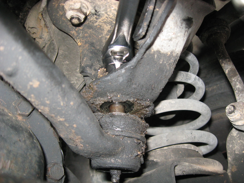
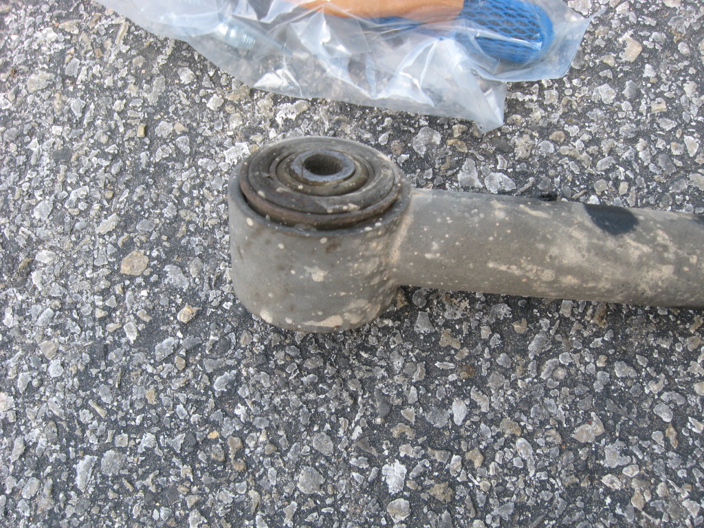
The bushing side was fine. Took a little hammering to get the bolt turning, but after that, no problems.
The hole looked a little oblong, but not enough that I wanted to do anything about it.
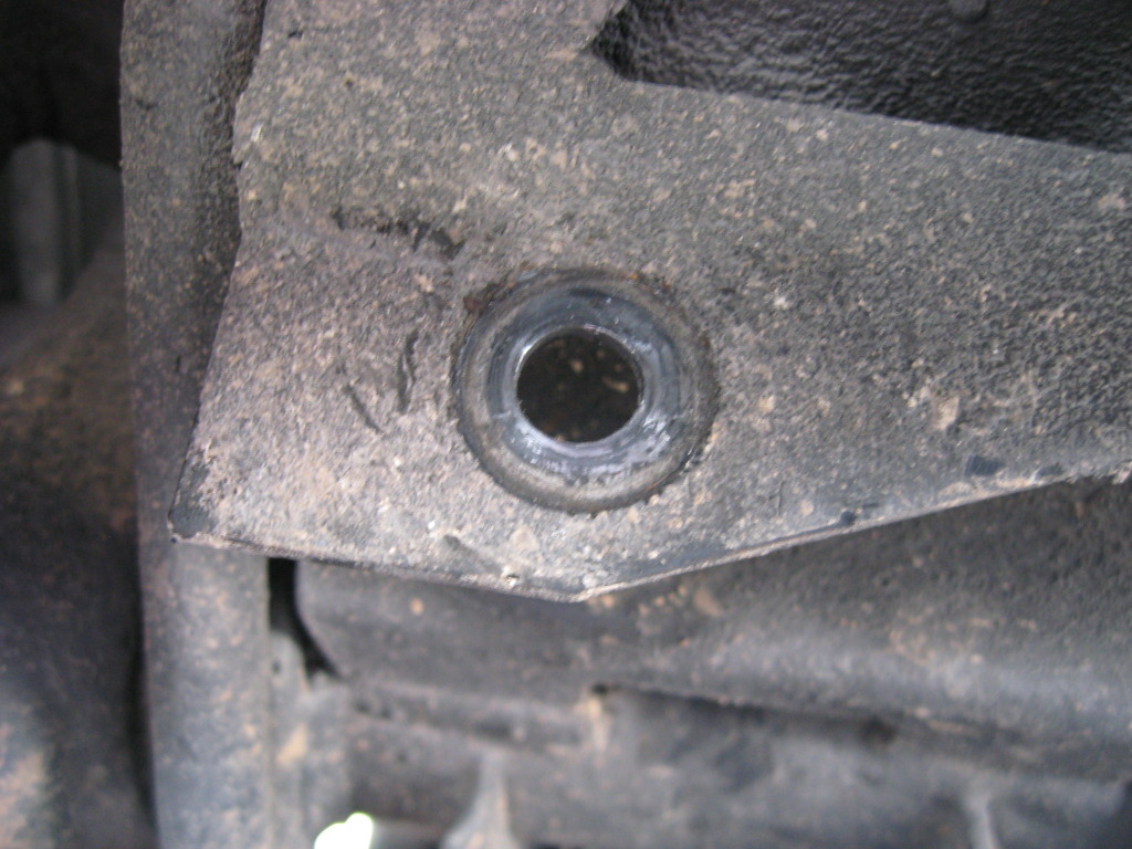
Once that came off, a bit of tugging and the track bar came free.
Pretty worn out, eh...?
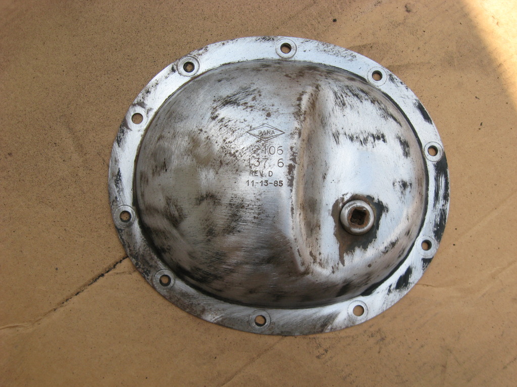
Finished pulling the D30 cover off.
Cleaned the covers off, then paint.
So, there's no room up there (sans lift) to fit this bottle so that a majority of the fluid goes in the diff....
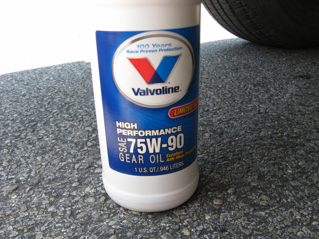
So, I grabbed the hose off my battery tester, shoved one end on the nozzle of the bottle and the other into the diff and started squeezing...worked alright to fill 'em up.
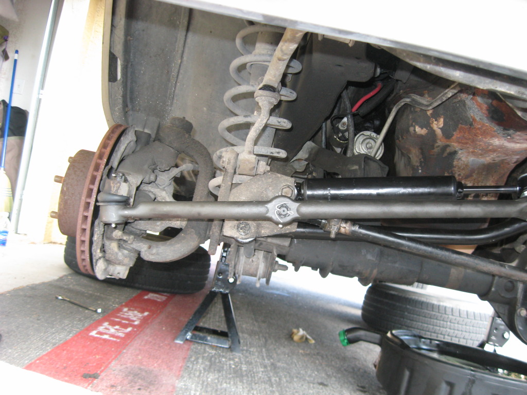
Now for the TREs....I jacked the car up and took the front tires off. Using my pickle fork, I hammered and hammered on the left inner (pitman arm) TRE to no avail. My neighbor, Child9, came out and surmised that my tool was inadequate, and lent me his 10# sledge for a little percussive maintenance, as he called it. Two whacks later, off it came
Popped the outer two off and the whole drag link / tie rod assembly hit the ground...I pulled the nut for the steering stabilizer and smashed the bolt trying to get it out. As soon as I hit it, I realized what a mistake that was as it boogered up the threads and I couldn't get the nut back on. Off to Advance for a replacement
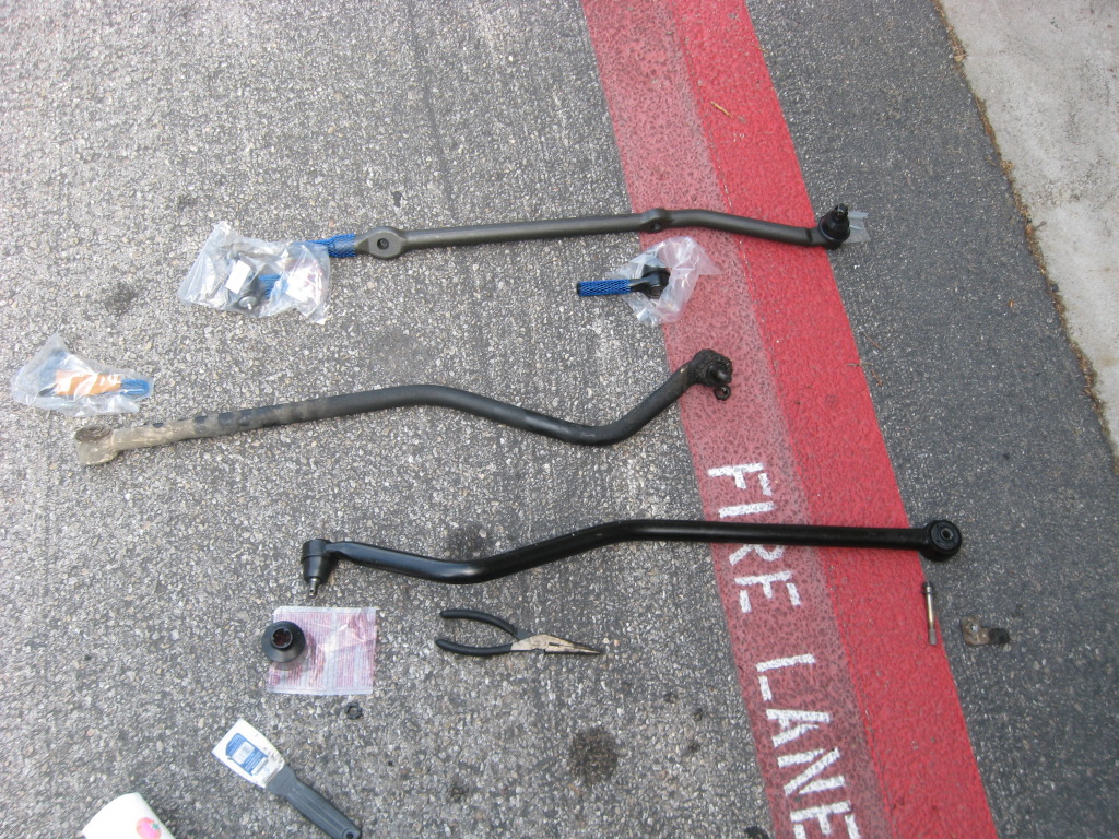
Using some PB, a pipe wrench, and lots of sweat, the old TREs came off, the new ones went on, and back onto the Jeep. I measured each end before removing it and put the new one on to the same measurement.
I then tried to put the new track bar on. Somehow, the axle had shifted over an inch toward the passenger side, so I could line up either the TRE or the bushing, but not both. I was confused. So I busted out the old ratchet strap, wrapped it around the D30 and a motor mount and pulled. Got it far enough over to get the track bar in.
Greased up the new boots, put the tires on, threw the tools in the garage to be dealt with at a later time, then off to Sears for an alignment!
Spent 10hrs under the Waggy on the 4th doing diff fluid, TREs, and track bar.
Note: Before taking your diff covers off, be sure you can remove the fill hole plugs....nothing worse than draining all your fluid and not being able to refill it...
Rear diff had a little leak, nothing bad.
Take all the bolts but the top one out -leave it in but loose.
Putty knife to create some space.
I have no idea the last time it was changed.
Inside the cover....nice little "water line"
Teeth looked alright.
Used a can of brake cleaner and sprayed the crap out of the inside and outside.
Set the cover aside and started on the front.
Got most of the bolts out, but that stupid track bar blocked two of them....maybe I wasn't trying hard enough, but I was going to be replacing it anyway, so off it came!
Pretty quickly, it became apparent the cause for my DW....the nut holding the left side of the track bar was loose and the TRE wasn't even press fit into the bracket....as I loosened the nut, the thing fell out! (BTW, that stupid cotter pin took almost an hour to get out....it sucked).
The bushing side was fine. Took a little hammering to get the bolt turning, but after that, no problems.
The hole looked a little oblong, but not enough that I wanted to do anything about it.
Once that came off, a bit of tugging and the track bar came free.
Pretty worn out, eh...?
Finished pulling the D30 cover off.
Cleaned the covers off, then paint.
So, there's no room up there (sans lift) to fit this bottle so that a majority of the fluid goes in the diff....
So, I grabbed the hose off my battery tester, shoved one end on the nozzle of the bottle and the other into the diff and started squeezing...worked alright to fill 'em up.
Now for the TREs....I jacked the car up and took the front tires off. Using my pickle fork, I hammered and hammered on the left inner (pitman arm) TRE to no avail. My neighbor, Child9, came out and surmised that my tool was inadequate, and lent me his 10# sledge for a little percussive maintenance, as he called it. Two whacks later, off it came
Popped the outer two off and the whole drag link / tie rod assembly hit the ground...I pulled the nut for the steering stabilizer and smashed the bolt trying to get it out. As soon as I hit it, I realized what a mistake that was as it boogered up the threads and I couldn't get the nut back on. Off to Advance for a replacement
Using some PB, a pipe wrench, and lots of sweat, the old TREs came off, the new ones went on, and back onto the Jeep. I measured each end before removing it and put the new one on to the same measurement.
I then tried to put the new track bar on. Somehow, the axle had shifted over an inch toward the passenger side, so I could line up either the TRE or the bushing, but not both. I was confused. So I busted out the old ratchet strap, wrapped it around the D30 and a motor mount and pulled. Got it far enough over to get the track bar in.
Greased up the new boots, put the tires on, threw the tools in the garage to be dealt with at a later time, then off to Sears for an alignment!
Last edited by letinsh; Jul 12, 2012 at 09:46 AM.


Thread Starter
Seasoned Member
Joined: Jan 2011
Posts: 303
Likes: 4
From: Austin
Year: 1987
Model: Wagoneer
Engine: 4.0
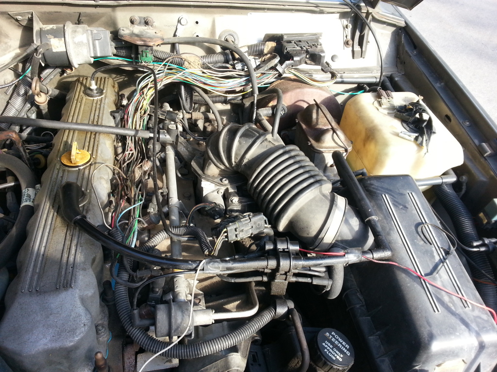
I replace the fuel pump because of an intermittent hesitation / bucking issue. I thought it was fuel delivery related, so I swapped it out. The problem got better, but never did go away. A week ago, it came back with a vengeance, so I wanted to check my sensors to make sure everything was kosher before looking elsewhere.
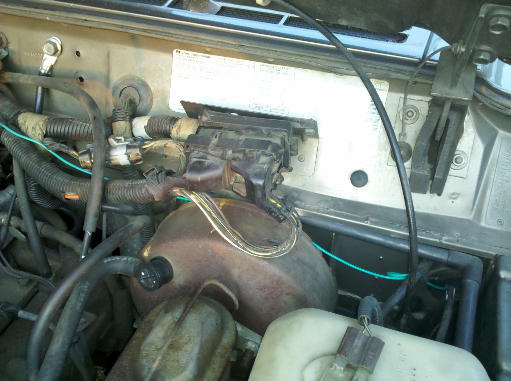
My under-hood wiring harness has been in need of maintenance for quite some time, so I did that concurrently.
Following this write-up by Cruiser54, I checked my TPS and grounds:
Depending on how I wiggled my harness, I'd get anywhere between 8ohms and 300ohms. I pulled all the wire wrap loom off of the harness and started tracing the ground wires.
I found the first splice, but the second would have required pulling quite a bit of tape off the harness, and the wife's bbq chicken was calling, so I held off on it.
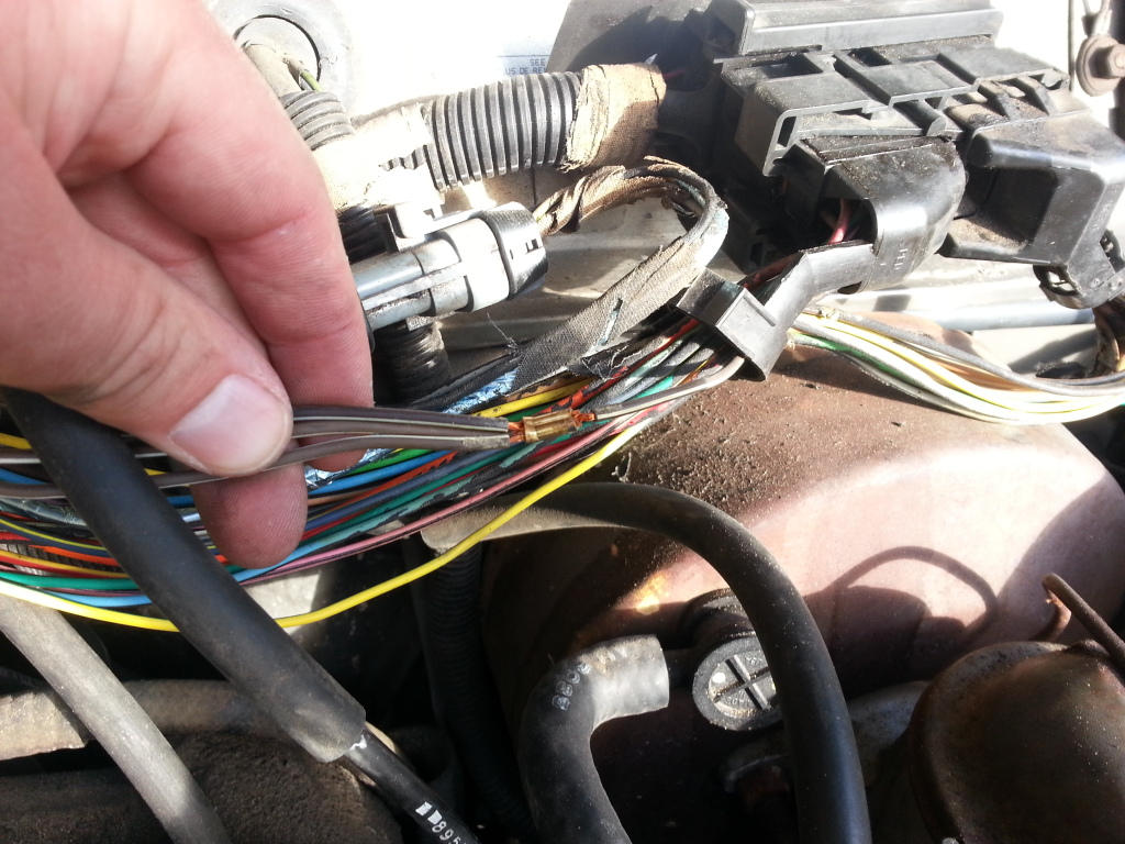
I don't own a soldering iron, so i used my brass brush and electronics cleaner, cleaned it off really well, re-crimped it, and wrapped it up again.
I also found another splice...I don't know what it's for. One black wire into about 6.
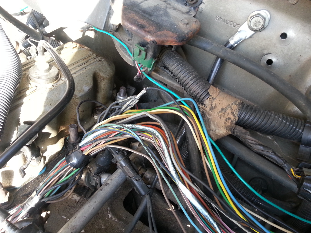
Cleaning and taping got me down to 1.8ohms with a 2-3 ohm variance as I wiggled the c101...good enough, and I'll address that problem later.
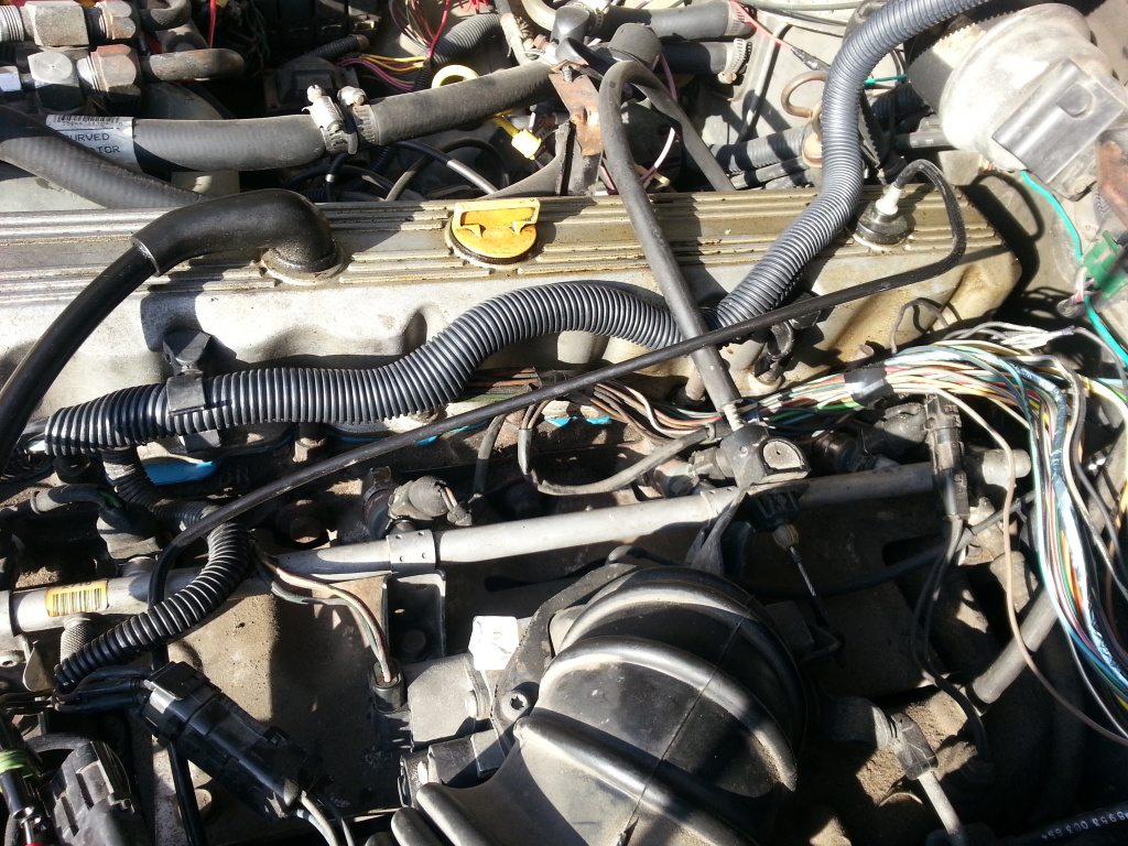
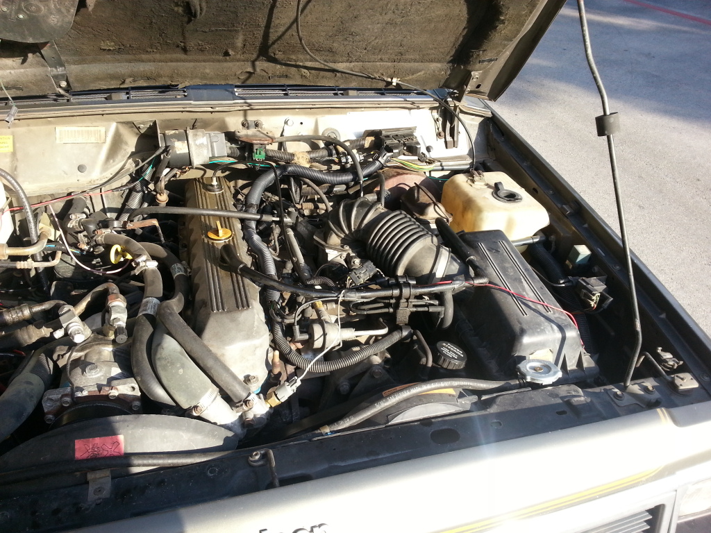
Time to put the new loom on the harness and clean things up.
Now to adjust the TPS, per cruiser54:
My reference was 4.95VDC X .17 = .84VDC for the proper output voltage.
My output voltage was .54VDC, so I adjusted it to be in-spec.
Let's see if this helps my hesitation issues...
My under-hood wiring harness has been in need of maintenance for quite some time, so I did that concurrently.
Following this write-up by Cruiser54, I checked my TPS and grounds:
Set your meter to measure Ohms. Be sure the key is in the OFF position. Using the positive (red) lead of your ohmmeter, probe the B terminal of the flat 3 wire connector of the TPS . The letters are embossed on the connector itself.
Touch the black lead of your meter to the negative battery post. Wiggle the wiring harness where it runs parallel to the valve cover and also near the MAP sensor mounted on the firewall. If you have an 87 or 88 with the C101 connector mounted on the firewall above the brake booster, wiggle it, too.
You want to see as close to 0 ohms of resistance as possible. And when wiggling the harnesses/connectors the resistance value should stay low. If there is a variance in the values when wiggling the wires, you have a poor crimp/connection in the wiring harness or a poor ground at the engine dipstick tube stud. On 87 and 88 models, you could have a poor connection at the C101 connector as well.
Find your Intake Air Temp sensor. It's the sensor just to the rear of the throttle body, has 2 wires, and screws into the intake manifold.
Where it's connector plugs into the harness you will see that one of the wires on the harness side is brown with a white stripe. Follow the brown with white stripe wire back into the harness. You'll have to open up the split-loom plastic sheathing to follow it. It will come to a splice with 2 other brown with white wires with duct tape over them. They're from the TPS and the CTS. The 3 wires will be spliced to a single wire headed toward the C101 connector if you have an 87 or 88. If you have an 89 or 90, you do not have the C101 bulkhead connector.
Now go to the MAP sensor. Follow the brown with white wire into the harness from there. You will find a splice with 2 more brown with white wires with duct tape over them. At the splice you will find the 3 wires connected to a single brown with white wire going toward the C101, or just along the firewall towards the engine if you have an 89 or 90. Along with the MAP sensor that you traced, they are the ECU sensor ground port and the diagnostic connector on the passenger inner fender.
You now have 2 sets of 3 brown with white wires, one near the firewall and one near the engine.
Cut the splices out of each set of wires eliminating not only the crappy factory splices, but also the single wire between them. Bring both sets of 3 wires together. Solder the 2 sets of wires together and insulate them properly with tape or shrink tubing.
Zip-tie up your new sensor loom to allow for engine movement. I prefer to cover it with some new split-loom or wrap it neatly with electrical tape when done.
Revised 03-09-12
I don't own a soldering iron, so i used my brass brush and electronics cleaner, cleaned it off really well, re-crimped it, and wrapped it up again.
I also found another splice...I don't know what it's for. One black wire into about 6.
Cleaning and taping got me down to 1.8ohms with a 2-3 ohm variance as I wiggled the c101...good enough, and I'll address that problem later.
Time to put the new loom on the harness and clean things up.
Now to adjust the TPS, per cruiser54:
RENIX TPS ADJUSTMENT
Before attempting to adjust your TPS be sure the throttle body has been recently cleaned.
It's especially important that the edges of the throttle butterfly are free of any carbon build-up.
IMPORTANT NOTE: Using the positive (red) lead of your ohmmeter, probe the B terminal of the flat 3 wire connector of the TPS . The letters are embossed on the connector itself.
Touch the black lead of your meter to the negative battery post.
If you see more than 1 ohm of resistance some modifications to the sensor ground harness will be necessary. The harness repair must be performed before proceeding. (see above)
The TPS has three wires in the connector and they're clearly embossed with the letters A,B, and C.
Wire "A" is positive.
Wire "B" is ground.
Key ON, measure voltage from "A" positive to "B" ground by back-probing the connectors..
Note the voltage reading--this is your REFERENCE voltage.
Key ON, back-probe the connector at wires "B" and "C". Measure the voltage. This is your OUTPUT voltage.
Your OUTPUT voltage needs to be seventeen percent of your REFERENCE voltage.
For example: 4.82 volts X .17=.82 volts. Adjust the TPS until you have achieved this percentage. If you can't achieve the correct output voltage replace the TPS and start over.
My output voltage was .54VDC, so I adjusted it to be in-spec.
Let's see if this helps my hesitation issues...
::CF Moderator::
Joined: Aug 2011
Posts: 43,971
Likes: 1,579
From: Prescott, Az
Year: 1990
Model: Cherokee (XJ)
Engine: 4.0
7/1/12
203,956
My power locks haven't worked since before I got it. You hit the button and it looks like it's trying, but nothing would happen. Stumbled across this writeup by Greg Smith over on NAXJA and thought I'd give it a shot.
It took me almost an hour to figure out that my XJ originally came with keyless entry and these two relays were part of that factory system. The light green and tan wires you need are on the XJ side (not the door side) of the black connector.
I cut them about 4" back from the connector. If I had to to it again, I'd cut them closer to the connector, so the relays don't sit under the carpet.

Instead of running power directly from the battery/starter terminal like the write up suggested, I spliced into the high side of the power going to the keyless entry relays. There was good voltage there (13.1VDC) and thought that'd be easier.

Next, the grounds. I removed the broken tabs from the original relays and used one of the bolts as my body ground. Plug 'em all up...
Lay them in and tape up the terminals.

Like I said, I'd prefer if they were behind the kick panel as opposed to sitting under the carpet, but none the less, now all 5 locks give a solid "THUNK" when you hit the lock/unlock button!
If the description of the wiring was confusing, here's a schematic and a link:
http://www.jeeptuning-foto.com/album...two-relays.pdf
203,956
My power locks haven't worked since before I got it. You hit the button and it looks like it's trying, but nothing would happen. Stumbled across this writeup by Greg Smith over on NAXJA and thought I'd give it a shot.
Power Door Lock Fix for Reluctant Locks on Pre 1991 Jeep Cherokees
(for post 90 models with a similar problem I woud check the relays in the passenger side kick
panel)
The Problem:
Some (usually not all) of the power door locks stop working, or more commonly work
inconsistently on the lock and/or unlock position. The problem usually starts when the Jeep gets
older and the locks become stiffer. Cold weather seems to cause the most problems. The rear
hatch and rear doors seem to the most troublesome since they are on the end of the circuit and
experience the largest voltage drop.
The Cause:
The cause is a design flaw which causes a loss of 2 volts. As the Jeep gets older and the locks
become stiffer and the connections develop some resistance the amount of voltage that gets
through the system is no longer enough to work the power locks near the end of the circuit. With
the pre 1991 wiring all the power for the power door locks passes through the passenger door
lock switch regardless of whether you trigger that switch, the driver�s side door switch or the
remote keyless opener (if you have it). Power leaves that switch going to the door locks through
the tan wire for unlock and the light green wire for lock.
The power goes from the passenger door switch to a splice in that door for the power lock in that
door and then goes out the door and into the kick panel in front of the door on the passenger side.
By the time the power gets to the kick panel it has lost about 2 volts. I replaced my passenger side
switch suspecting a bad switch but still lost 2 volts out of the switch. I then did a full continuity and
resistance test on the switch per the factory service manual and found no problems. I have never
figured out why this happens but apparently Jeep could not either since they changed the wiring
starting in 1991 to compensate for this problem. (Note the wiring change can be done like the post
1990 models but the fix I provide below is a lot easier in my opinion.) After the now lower voltage
gets to the passenger side kick panel it goes under the carpet and over to the driver�s side and
hits a master splice under the front floor carpet for the wires going to the driver�s side front and
rear doors and the passenger side rear door. I unwrapped the tape around the splices and
checked all the splices and they were clean and tight. Then I measured the voltage at the
remaining power locks. By the time the voltage gets through the master splice is loses another 2+
volts and is not enough to power the locks consistently when they become stiff from old age or
cold weather.
The Fix/Repair:
First make sure you are getting around 12 volts of power to your passenger side door switch
directly or when you trigger the lock or unlock switch from the driver�s side or by the remote. You
can test the voltage with a multi-meter at the wire harness connector in the passenger-side kick
panel where the dark green, white and red wires go into the front door.
Assuming you have a full voltage supply to the passenger side switch, the fix is to install two
relays in the passenger-side kick panel on the lock and unlock wires coming from the passenger
side switch. The relays will increase voltage back up to 12 volts to compensate for the loss
caused by the passenger side switch. With the voltage increase provided by the relays, the
voltage at the remaining power door locks is increased by approximately 2 volts, enough to power
all the locks, even in cold weather. This of course assumes that no wiring problems exist from the
splices to the door locks. If you still have a problem at a particular door lock measure the voltage
and make sure it is over 9 volts. With my fix it should be closer to 10 and perhaps 9 at the rear
hatch.
The relays to use are 5 blade, 12 volt, 30 amp minimum rated relays with blades marked 85, 86,
87, 87a and 30. These relays are the same as those used for the keyless remote relays found in
the passenger-side kick panel so you may find them cheap at the bone yard. You can also find
them in automotive electric supply stores. Look in the section that has lighting upgrade supplies.
For an easier install it is also best to buy wiring sockets that fit the relays. Here is a link to
partsexpress.com an online supplier that has relays and sockets at reasonable prices. I used 2
bosch relays # 330-070 and 2 sockets # 330-075 (although 1 dual socket 330-078 could be used I
believe). http://www.partsexpress.com/webpage....oup_ID=31&SO=2
Here is how I did the wiring: I used the two 12v relays. They have 5 blades: 86 is trigger pwr from
the passenger dr switch; 85 is ground; 87 is the new pwr source; 30 is the path to the lock and
87a is to ground (in this application). I cut the Lgreen and tan wire about 5 inches forward (toward
the front of the Jeep) of the wire harness connector that connects the wires to the wires coming
out of the passenger frnt dr. In this example I attached the tan unlock wire coming from the
passenger frnt door to 86 and 85 to ground; 30 is attached to the tan wire going to the door locks;
and 87a is to ground. I used the new 10 gauge pwr line I had previously run to the battery/starter
relay post with a 30 amp inline fuse. You can take off pwr from a splice on the red pwr going into
the passenger door instead. (The same approach is used for the lgreen wire using the other new
relay for for the lock circuit.) The key to making this work was 87a to ground. When the lgreen or
tan wire are not in pwr mode they provide ground path to ground through the driver�s side switch.
With my new relays I substituted a new body ground instead. As a result I increased voltage and
created new better grounds. The locks now all slam open and closed even in very cold weather.
Hope this helps. At least 30 people I have heard from have done this mod with great success.
Greg
I pulled my kick panel off and was thrown for a loop when I saw these two relays. They looked like this mod had already been done:(for post 90 models with a similar problem I woud check the relays in the passenger side kick
panel)
The Problem:
Some (usually not all) of the power door locks stop working, or more commonly work
inconsistently on the lock and/or unlock position. The problem usually starts when the Jeep gets
older and the locks become stiffer. Cold weather seems to cause the most problems. The rear
hatch and rear doors seem to the most troublesome since they are on the end of the circuit and
experience the largest voltage drop.
The Cause:
The cause is a design flaw which causes a loss of 2 volts. As the Jeep gets older and the locks
become stiffer and the connections develop some resistance the amount of voltage that gets
through the system is no longer enough to work the power locks near the end of the circuit. With
the pre 1991 wiring all the power for the power door locks passes through the passenger door
lock switch regardless of whether you trigger that switch, the driver�s side door switch or the
remote keyless opener (if you have it). Power leaves that switch going to the door locks through
the tan wire for unlock and the light green wire for lock.
The power goes from the passenger door switch to a splice in that door for the power lock in that
door and then goes out the door and into the kick panel in front of the door on the passenger side.
By the time the power gets to the kick panel it has lost about 2 volts. I replaced my passenger side
switch suspecting a bad switch but still lost 2 volts out of the switch. I then did a full continuity and
resistance test on the switch per the factory service manual and found no problems. I have never
figured out why this happens but apparently Jeep could not either since they changed the wiring
starting in 1991 to compensate for this problem. (Note the wiring change can be done like the post
1990 models but the fix I provide below is a lot easier in my opinion.) After the now lower voltage
gets to the passenger side kick panel it goes under the carpet and over to the driver�s side and
hits a master splice under the front floor carpet for the wires going to the driver�s side front and
rear doors and the passenger side rear door. I unwrapped the tape around the splices and
checked all the splices and they were clean and tight. Then I measured the voltage at the
remaining power locks. By the time the voltage gets through the master splice is loses another 2+
volts and is not enough to power the locks consistently when they become stiff from old age or
cold weather.
The Fix/Repair:
First make sure you are getting around 12 volts of power to your passenger side door switch
directly or when you trigger the lock or unlock switch from the driver�s side or by the remote. You
can test the voltage with a multi-meter at the wire harness connector in the passenger-side kick
panel where the dark green, white and red wires go into the front door.
Assuming you have a full voltage supply to the passenger side switch, the fix is to install two
relays in the passenger-side kick panel on the lock and unlock wires coming from the passenger
side switch. The relays will increase voltage back up to 12 volts to compensate for the loss
caused by the passenger side switch. With the voltage increase provided by the relays, the
voltage at the remaining power door locks is increased by approximately 2 volts, enough to power
all the locks, even in cold weather. This of course assumes that no wiring problems exist from the
splices to the door locks. If you still have a problem at a particular door lock measure the voltage
and make sure it is over 9 volts. With my fix it should be closer to 10 and perhaps 9 at the rear
hatch.
The relays to use are 5 blade, 12 volt, 30 amp minimum rated relays with blades marked 85, 86,
87, 87a and 30. These relays are the same as those used for the keyless remote relays found in
the passenger-side kick panel so you may find them cheap at the bone yard. You can also find
them in automotive electric supply stores. Look in the section that has lighting upgrade supplies.
For an easier install it is also best to buy wiring sockets that fit the relays. Here is a link to
partsexpress.com an online supplier that has relays and sockets at reasonable prices. I used 2
bosch relays # 330-070 and 2 sockets # 330-075 (although 1 dual socket 330-078 could be used I
believe). http://www.partsexpress.com/webpage....oup_ID=31&SO=2
Here is how I did the wiring: I used the two 12v relays. They have 5 blades: 86 is trigger pwr from
the passenger dr switch; 85 is ground; 87 is the new pwr source; 30 is the path to the lock and
87a is to ground (in this application). I cut the Lgreen and tan wire about 5 inches forward (toward
the front of the Jeep) of the wire harness connector that connects the wires to the wires coming
out of the passenger frnt dr. In this example I attached the tan unlock wire coming from the
passenger frnt door to 86 and 85 to ground; 30 is attached to the tan wire going to the door locks;
and 87a is to ground. I used the new 10 gauge pwr line I had previously run to the battery/starter
relay post with a 30 amp inline fuse. You can take off pwr from a splice on the red pwr going into
the passenger door instead. (The same approach is used for the lgreen wire using the other new
relay for for the lock circuit.) The key to making this work was 87a to ground. When the lgreen or
tan wire are not in pwr mode they provide ground path to ground through the driver�s side switch.
With my new relays I substituted a new body ground instead. As a result I increased voltage and
created new better grounds. The locks now all slam open and closed even in very cold weather.
Hope this helps. At least 30 people I have heard from have done this mod with great success.
Greg
It took me almost an hour to figure out that my XJ originally came with keyless entry and these two relays were part of that factory system. The light green and tan wires you need are on the XJ side (not the door side) of the black connector.
I cut them about 4" back from the connector. If I had to to it again, I'd cut them closer to the connector, so the relays don't sit under the carpet.
Instead of running power directly from the battery/starter terminal like the write up suggested, I spliced into the high side of the power going to the keyless entry relays. There was good voltage there (13.1VDC) and thought that'd be easier.
Next, the grounds. I removed the broken tabs from the original relays and used one of the bolts as my body ground. Plug 'em all up...
Lay them in and tape up the terminals.
Like I said, I'd prefer if they were behind the kick panel as opposed to sitting under the carpet, but none the less, now all 5 locks give a solid "THUNK" when you hit the lock/unlock button!
If the description of the wiring was confusing, here's a schematic and a link:
http://www.jeeptuning-foto.com/album...two-relays.pdf
Why isn't this a sticky?
Thread Starter
Seasoned Member
Joined: Jan 2011
Posts: 303
Likes: 4
From: Austin
Year: 1987
Model: Wagoneer
Engine: 4.0
207,xxx
Got some new shoes for the waggy
Firestone Destination A/Ts
215/75-15's
I really dig 'em....suddenly my xj has stopped wandering all over the road
firestone hasn't had any recalls in a few years, so I'm safe, right?
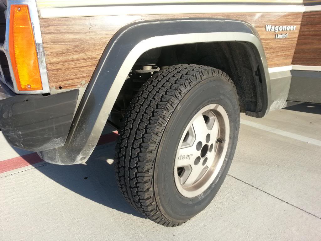
Got some new shoes for the waggy
Firestone Destination A/Ts
215/75-15's
I really dig 'em....suddenly my xj has stopped wandering all over the road
firestone hasn't had any recalls in a few years, so I'm safe, right?
CF Veteran
Joined: Feb 2011
Posts: 3,074
Likes: 0
From: Bergen County, New Jersey U.S.A.
Year: 1990 Laredo
Model: Cherokee
Engine: 4.0 Inline 6 Renix
great truck i love the waggys.. keep up the nice work.... you must bake in that truck with no tint on the windows tho... How hot does it get down there??
Thread Starter
Seasoned Member
Joined: Jan 2011
Posts: 303
Likes: 4
From: Austin
Year: 1987
Model: Wagoneer
Engine: 4.0
209,250
11/24-11/25

So, all the guides said this was an afternoon job, simple, just dirty.
BS. I started to take pictures to include in this post, but I got so fed up with the process, I quit with the camera...
10 minutes to remove starter (after disconnecting battery).
30 minutes to remove all the necessary bolts/screws/brackets, etc.
5 minutes to break the seal and drop the pan.
5 hours to get the pan out.
Stupid geometry problem. There just isn't very much room with a stock setup between the front axle, bell housing, track bar, and oil pump pickup. In the end, I had removed lower shock bolts, sway bar links, upper track bar TRE, pitman arm TRE, steering dampener (both sides cuz i boogered up the threads on the tie rod bolt and needed to replace it), loosened up the tranny cross-member bolts and jacket the tranny up.
THEN, with some praying, cursing, wiggling, sweet-talking and general pulling and pushing, it came out.
Cleaned it off with my wire wheel, painted it, and set it aside to dry.
Now, for the actual thing I came to fix....
I didn't have an extension long enough to get to the bearing cap bolts, so off to Sears. I also didn't have a cheater bar, so I went to Lowes to pick up some pipe to slip over the handle of my ratchet. They would only sell me a 4 ft section for $13. I didn't want to do that, so off to Home Depot and they GAVE me a 2ft section and a 3ft section from their scrap pile. I love Home Depot.
Back to the garage. Bolts came out fine, cap came off, got the old seal out with just a bit of tapping. Coated the new one with oil and she slid right in.
Applied RTV to the cap and bolted it back in.
Done for the night.
Came back in the morning, made sure my gasket surfaces were clean and I zip tied my new Felpro gasket to the oil pan (thanks for the tip, Beerguyatx) and set about trying to get the pan back in. I hadn't changed a thing, but it took 3 more hours to get that pan back in.
Add rtv in the requisite areas and set about bolting it back in. Torqued everything down, reattached all the steering and suspension components I had detached, lubed up the grease fittings, put the tires on and lowered the waggy down. Filled up with fresh oil and called it a night.
Drove to work today (25 miles) nary a drip
What a pain, but it's done!
11/24-11/25
So, all the guides said this was an afternoon job, simple, just dirty.
BS. I started to take pictures to include in this post, but I got so fed up with the process, I quit with the camera...
10 minutes to remove starter (after disconnecting battery).
30 minutes to remove all the necessary bolts/screws/brackets, etc.
5 minutes to break the seal and drop the pan.
5 hours to get the pan out.
Stupid geometry problem. There just isn't very much room with a stock setup between the front axle, bell housing, track bar, and oil pump pickup. In the end, I had removed lower shock bolts, sway bar links, upper track bar TRE, pitman arm TRE, steering dampener (both sides cuz i boogered up the threads on the tie rod bolt and needed to replace it), loosened up the tranny cross-member bolts and jacket the tranny up.
THEN, with some praying, cursing, wiggling, sweet-talking and general pulling and pushing, it came out.
Cleaned it off with my wire wheel, painted it, and set it aside to dry.
Now, for the actual thing I came to fix....
I didn't have an extension long enough to get to the bearing cap bolts, so off to Sears. I also didn't have a cheater bar, so I went to Lowes to pick up some pipe to slip over the handle of my ratchet. They would only sell me a 4 ft section for $13. I didn't want to do that, so off to Home Depot and they GAVE me a 2ft section and a 3ft section from their scrap pile. I love Home Depot.
Back to the garage. Bolts came out fine, cap came off, got the old seal out with just a bit of tapping. Coated the new one with oil and she slid right in.
Applied RTV to the cap and bolted it back in.
Done for the night.
Came back in the morning, made sure my gasket surfaces were clean and I zip tied my new Felpro gasket to the oil pan (thanks for the tip, Beerguyatx) and set about trying to get the pan back in. I hadn't changed a thing, but it took 3 more hours to get that pan back in.
Add rtv in the requisite areas and set about bolting it back in. Torqued everything down, reattached all the steering and suspension components I had detached, lubed up the grease fittings, put the tires on and lowered the waggy down. Filled up with fresh oil and called it a night.
Drove to work today (25 miles) nary a drip
What a pain, but it's done!
Last edited by letinsh; Nov 26, 2012 at 10:57 AM.