
P0107 CEL code

Thread Starter
Senior Member
Joined: Jan 2012
Posts: 596
Likes: 0
From: Kansas City
Year: 1998
Model: Cherokee
Engine: 4.0L
So this code popped up the other day, and my Jeep started running and idling in a way that felt like the motor was misfiring. The Jeep did die at idle a couple times, but starts right back up right away. The code says "Manifold Absolute Pressure/Barometric Pressure Circuit Low Input". I replaced the MAP sensor, still get the hesitation and poor performance. I don't have the tools to check and see if I'm getting 5v to the MAP sensor, but I don't know why anything would have changed. Anyone have a similar issue? Jeep is a 98
CF Veteran
Joined: Jul 2010
Posts: 4,930
Likes: 3
From: 802
Year: 99
Model: Cherokee
Engine: 4.0
Possibly o2 sensors? That can account for similar symptoms. Other things might be fuel delivery. The pump/filter assembly is in the tank and Dropping it is the only was to know for sure. But this way you can kill 3 birds with one stone; the pump, filter and the tanks cleanliness. How is your overall ignition system condition? Good clean grounds? What about the TB- have you checked it's condition?
Thread Starter
Senior Member
Joined: Jan 2012
Posts: 596
Likes: 0
From: Kansas City
Year: 1998
Model: Cherokee
Engine: 4.0L
I pulled the air intake tube off the TB when I replaced the MAP sensor. TB didnt look dirty on the butterfly at all. As for o2 sensors, wouldn't that trigger a CEL code if it went bad?
As for ignition system, I havent really looked at it too much. Under the hood is a little dirty because of water and mud splashing up in there, but it's not terrible.
As for ignition system, I havent really looked at it too much. Under the hood is a little dirty because of water and mud splashing up in there, but it's not terrible.

CF Veteran


Joined: Nov 2010
Posts: 5,841
Likes: 117
From: In the middle of Minnesota!
Year: 1999
Model: Cherokee
Engine: 4.0
Trust your OBD on this one; something is amiss with your MAP sensor circuit. That includes the sensor, connector, wiring, input voltage and vacuum.
Along with verifying that you're getting juice to the sensor (buy a meter; they're $10 and everyone needs one), perform a very close inspection of the vacuum line leading to the map sensor.
First, be sure that the vacuum line is pulling good vacuum. If it is, inspect for cracking, especially where it fits onto the sensor.
Any vacuum leak and the sensor won't work properly.
Thread Starter
Senior Member
Joined: Jan 2012
Posts: 596
Likes: 0
From: Kansas City
Year: 1998
Model: Cherokee
Engine: 4.0L
Replaced the map, tps, and iac. Still having the same problem. Map is getting the 5v its supposed to. Vacuum line looked fine... I'm kind of at a loss here.
Where's the ground at for this circuit? I want to clean it up and make sure it's grounding properly.
Where's the ground at for this circuit? I want to clean it up and make sure it's grounding properly.
Last edited by zimdogg; Apr 13, 2012 at 01:20 PM.
Thread Starter
Senior Member
Joined: Jan 2012
Posts: 596
Likes: 0
From: Kansas City
Year: 1998
Model: Cherokee
Engine: 4.0L
Nothing? I really don't want to have to take this thing into shop.
Anyone have an extra PCM laying around that I could swap with mine and see if it's a bad computer?
Anyone have an extra PCM laying around that I could swap with mine and see if it's a bad computer?
Trending Topics
Thread Starter
Senior Member
Joined: Jan 2012
Posts: 596
Likes: 0
From: Kansas City
Year: 1998
Model: Cherokee
Engine: 4.0L
Changed upstream o2 sensor and cleaned the grounds real well again. Still not running right.
Can't believe nobody has dealt with these issues before.
Can't believe nobody has dealt with these issues before.
CF Veteran
Joined: Aug 2010
Posts: 8,357
Likes: 103
From: Canton, MI
Year: 1999
Model: Cherokee
Engine: 4.0
Here's what he diagnostics manual says:
P0107-MAP SENSOR VOLTAGE TOO LOW
Possible Causes
PCM MAP SENSOR SIGNAL
The following is not from the diagnostics manual, it's based on what I've seen.
With the ignition switch in RUN, engine off:
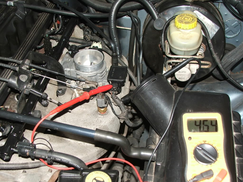
Detach and look at the MAP body harness connector, pin cavity 3 will be the 5 volt supply from the PCM (Pin cavity 3 is on your right- looking at the harness connector), read from Pin 1, ground, (on your left is ground inside the PCM) to pin 3. You should get approximately 5 volts.
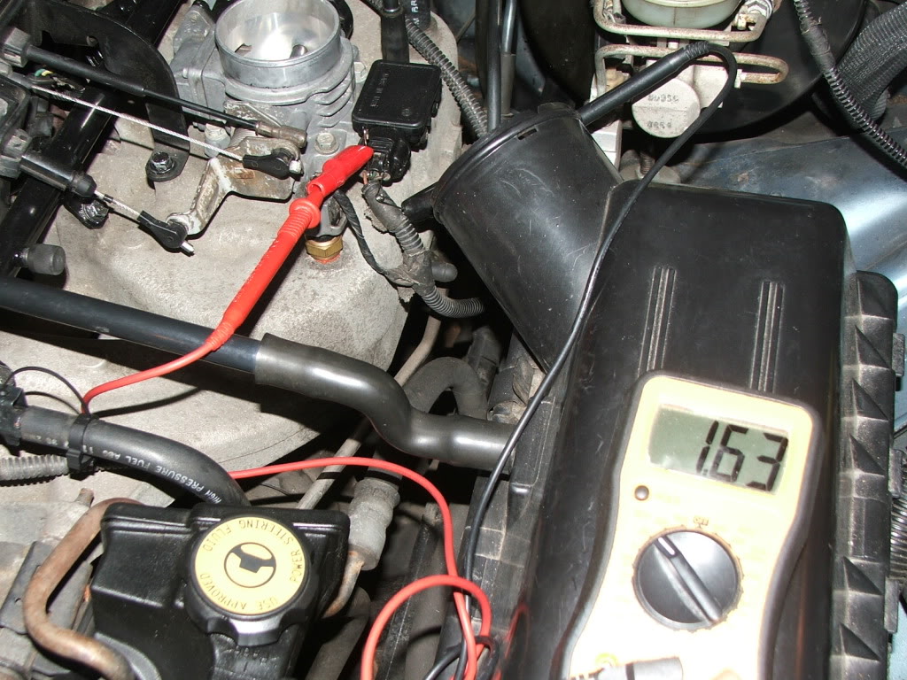
Reconnect the MAP harness connector. At the back of the MAP harness connector, back probe the Dark Green/Red tracer wire (MAP sensor signal pin 2) and back probe the Brown/Yellow tracer wire (pin 1). Connect your voltmeter (+) lead to the DG/RD wire back probe and the (-) lead to the BR/Y wire back probe. Turn key to RUN, engine not running, you should see around 4.6 to 4.7 volts. Start engine, at warm idle you should read approximately 1.63 volts, advance the throttle off idle, the voltage should drop to 1.30 volts or so, keep advancing the throttle, the voltage will remain around 1.20 to 1.36 volts.
If the signal voltage is bad the DG/RD signal wire to the PCM may be open or shorted to ground.
P0107-MAP SENSOR VOLTAGE TOO LOW
Possible Causes
MAP SENSOR SIGNAL CIRCUIT SHORTED TO GROUND
INTERMITTENT CONDITION
5 VOLT SUPPLY CIRCUIT SHORTED TO GROUND
5 VOLT SUPPLY CIRCUIT OPEN
MAP SENSOR INTERNAL FAILURE
PCM 5 VOLT SUPPLY CIRCUIT
INTERMITTENT CONDITION
5 VOLT SUPPLY CIRCUIT SHORTED TO GROUND
5 VOLT SUPPLY CIRCUIT OPEN
MAP SENSOR INTERNAL FAILURE
PCM 5 VOLT SUPPLY CIRCUIT
PCM MAP SENSOR SIGNAL
The following is not from the diagnostics manual, it's based on what I've seen.
With the ignition switch in RUN, engine off:
Detach and look at the MAP body harness connector, pin cavity 3 will be the 5 volt supply from the PCM (Pin cavity 3 is on your right- looking at the harness connector), read from Pin 1, ground, (on your left is ground inside the PCM) to pin 3. You should get approximately 5 volts.
Reconnect the MAP harness connector. At the back of the MAP harness connector, back probe the Dark Green/Red tracer wire (MAP sensor signal pin 2) and back probe the Brown/Yellow tracer wire (pin 1). Connect your voltmeter (+) lead to the DG/RD wire back probe and the (-) lead to the BR/Y wire back probe. Turn key to RUN, engine not running, you should see around 4.6 to 4.7 volts. Start engine, at warm idle you should read approximately 1.63 volts, advance the throttle off idle, the voltage should drop to 1.30 volts or so, keep advancing the throttle, the voltage will remain around 1.20 to 1.36 volts.
If the signal voltage is bad the DG/RD signal wire to the PCM may be open or shorted to ground.
Last edited by CCKen; Apr 21, 2012 at 02:45 PM. Reason: Corrected procedure and back probe voltge readings
CF Veteran
Joined: Aug 2010
Posts: 8,357
Likes: 103
From: Canton, MI
Year: 1999
Model: Cherokee
Engine: 4.0
Here's what he diagnostics manual says:
P0107-MAP SENSOR VOLTAGE TOO LOW
Possible Causes
PCM MAP SENSOR SIGNAL
The following is not from the diagnostics manual, it's based on what I've seen.
With the ignition switch in RUN, engine off:
Detach and look at the MAP body harness connector, pin cavity 3 will be the 5 volt supply from the PCM (Pin cavity 3 is on your right- looking at the harness connector), read from Pin 1, ground, (on your left is ground inside the PCM) to pin 3. You should get approximately 5 volts.
Reconnect the MAP harness connector. At the back of the MAP harness connector, back probe the Dark Green/Red tracer wire (MAP sensor signal pin 2) and back probe the Brown/Yellow tracer wire (pin 1). Connect your voltmeter (+) lead to the DG/RD wire back probe and the (-) lead to the BR/Y wire back probe. Turn key to RUN, engine not running, you should see around 4.6 to 4.7 volts. Start engine, at warm idle you should read approximately 1.63 volts, advance the throttle off idle, the voltage should drop to 1.30 volts or so, keep advancing the throttle, the voltage will remain around 1.20 to 1.36 volts.
If the signal voltage is bad the DG/RD signal wire to the PCM may be open or shorted to ground.
P0107-MAP SENSOR VOLTAGE TOO LOW
Possible Causes
MAP SENSOR SIGNAL CIRCUIT SHORTED TO GROUND
INTERMITTENT CONDITION
5 VOLT SUPPLY CIRCUIT SHORTED TO GROUND
5 VOLT SUPPLY CIRCUIT OPEN
MAP SENSOR INTERNAL FAILURE
PCM 5 VOLT SUPPLY CIRCUIT
INTERMITTENT CONDITION
5 VOLT SUPPLY CIRCUIT SHORTED TO GROUND
5 VOLT SUPPLY CIRCUIT OPEN
MAP SENSOR INTERNAL FAILURE
PCM 5 VOLT SUPPLY CIRCUIT
PCM MAP SENSOR SIGNAL
The following is not from the diagnostics manual, it's based on what I've seen.
With the ignition switch in RUN, engine off:
Detach and look at the MAP body harness connector, pin cavity 3 will be the 5 volt supply from the PCM (Pin cavity 3 is on your right- looking at the harness connector), read from Pin 1, ground, (on your left is ground inside the PCM) to pin 3. You should get approximately 5 volts.
Reconnect the MAP harness connector. At the back of the MAP harness connector, back probe the Dark Green/Red tracer wire (MAP sensor signal pin 2) and back probe the Brown/Yellow tracer wire (pin 1). Connect your voltmeter (+) lead to the DG/RD wire back probe and the (-) lead to the BR/Y wire back probe. Turn key to RUN, engine not running, you should see around 4.6 to 4.7 volts. Start engine, at warm idle you should read approximately 1.63 volts, advance the throttle off idle, the voltage should drop to 1.30 volts or so, keep advancing the throttle, the voltage will remain around 1.20 to 1.36 volts.
If the signal voltage is bad the DG/RD signal wire to the PCM may be open or shorted to ground.
Ignition RUN, engine off.
Engine running at warm idle.
Thread Starter
Senior Member
Joined: Jan 2012
Posts: 596
Likes: 0
From: Kansas City
Year: 1998
Model: Cherokee
Engine: 4.0L
Here's what he diagnostics manual says:
P0107-MAP SENSOR VOLTAGE TOO LOW
Possible Causes
PCM MAP SENSOR SIGNAL
The following is not from the diagnostics manual, it's based on what I've seen.
With the ignition switch in RUN, engine off:
Detach and look at the MAP body harness connector, pin cavity 3 will be the 5 volt supply from the PCM (Pin cavity 3 is on your right- looking at the harness connector), read from Pin 1, ground, (on your left is ground inside the PCM) to pin 3. You should get approximately 5 volts.
Reconnect the MAP harness connector. At the back of the MAP harness connector, back probe the Dark Green/Red tracer wire (MAP sensor signal pin 2) and back probe the Brown/Yellow tracer wire (pin 1). Connect your voltmeter (+) lead to the DG/RD wire back probe and the (-) lead to the BR/Y wire back probe. Turn key to RUN, engine not running, you should see around 4.6 to 4.7 volts. Start engine, at warm idle you should read approximately 1.63 volts, advance the throttle off idle, the voltage should drop to 1.30 volts or so, keep advancing the throttle, the voltage will remain around 1.20 to 1.36 volts.
If the signal voltage is bad the DG/RD signal wire to the PCM may be open or shorted to ground.
P0107-MAP SENSOR VOLTAGE TOO LOW
Possible Causes
MAP SENSOR SIGNAL CIRCUIT SHORTED TO GROUND
INTERMITTENT CONDITION
5 VOLT SUPPLY CIRCUIT SHORTED TO GROUND
5 VOLT SUPPLY CIRCUIT OPEN
MAP SENSOR INTERNAL FAILURE
PCM 5 VOLT SUPPLY CIRCUIT
INTERMITTENT CONDITION
5 VOLT SUPPLY CIRCUIT SHORTED TO GROUND
5 VOLT SUPPLY CIRCUIT OPEN
MAP SENSOR INTERNAL FAILURE
PCM 5 VOLT SUPPLY CIRCUIT
PCM MAP SENSOR SIGNAL
The following is not from the diagnostics manual, it's based on what I've seen.
With the ignition switch in RUN, engine off:
Detach and look at the MAP body harness connector, pin cavity 3 will be the 5 volt supply from the PCM (Pin cavity 3 is on your right- looking at the harness connector), read from Pin 1, ground, (on your left is ground inside the PCM) to pin 3. You should get approximately 5 volts.
Reconnect the MAP harness connector. At the back of the MAP harness connector, back probe the Dark Green/Red tracer wire (MAP sensor signal pin 2) and back probe the Brown/Yellow tracer wire (pin 1). Connect your voltmeter (+) lead to the DG/RD wire back probe and the (-) lead to the BR/Y wire back probe. Turn key to RUN, engine not running, you should see around 4.6 to 4.7 volts. Start engine, at warm idle you should read approximately 1.63 volts, advance the throttle off idle, the voltage should drop to 1.30 volts or so, keep advancing the throttle, the voltage will remain around 1.20 to 1.36 volts.
If the signal voltage is bad the DG/RD signal wire to the PCM may be open or shorted to ground.
CF Veteran
Joined: Aug 2010
Posts: 8,357
Likes: 103
From: Canton, MI
Year: 1999
Model: Cherokee
Engine: 4.0
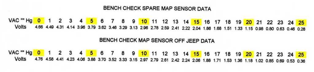
With key in RUN/engine off you should see something a little less than the PCM 5 volt input based on the barometric pressure - around 30 "hg. When the engine starts the pressure (vacuum) at the MAP will be something less than Baro - around 18 - 20 "hg. The chart below shows the data I generated bench testing two MAP sensors using a 5 volt power supply and a brake bleeder vacuum hand pump. You can see that at "0" vacuum (Baro) the voltage is somewhat less than 5 volts and at around 18 -20 "hg the voltage is around 1.XX volts.
Here's a diagram of the MAP circuit.
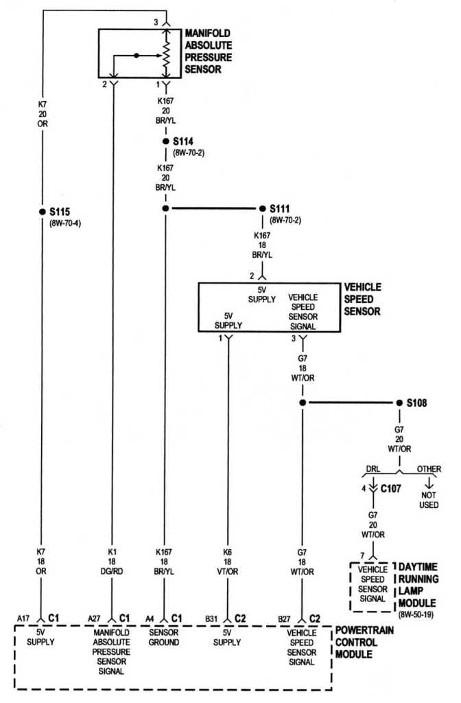
Try reading from the DG/RD wire (signal) to chassis ground and see what you get.
You may be at the last of the P0107 possible causes..PCM MAP SENSOR SIGNAL
Here's the steps outlined in the diagnostics manual:
Turn the ignition off.
Disconnect the MAP Sensor harness connector.
Disconnect the PCM harness connector. (C1 - Black)
Measure the resistance of the MAP Sensor Signal circuit in the MAP Sensor harness
connector to ground.
Is the resistance below 5 ohms?
Disconnect the MAP Sensor harness connector.
Disconnect the PCM harness connector. (C1 - Black)
Measure the resistance of the MAP Sensor Signal circuit in the MAP Sensor harness
connector to ground.
Is the resistance below 5 ohms?
Yes ?
Repair the MAP Sensor Signal circuit for a short to ground.
Thread Starter
Senior Member
Joined: Jan 2012
Posts: 596
Likes: 0
From: Kansas City
Year: 1998
Model: Cherokee
Engine: 4.0L
.02v was with engine off in run position. This is my first time really using a voltometer, so I hope I have everything on the correct settings. Electrical is not my cup of tea whatsoever. For the test to grounding the signal wire to the chassis, I assume (+) lead on the signal wire, and (-) lead to chassis?
I really appreciate your help.
I really appreciate your help.
Last edited by zimdogg; Apr 23, 2012 at 01:45 PM.
Thread Starter
Senior Member
Joined: Jan 2012
Posts: 596
Likes: 0
From: Kansas City
Year: 1998
Model: Cherokee
Engine: 4.0L
When I run the dg/rd wire from the map connector to the pcm pin, I'm getting anywhere from 11 to 30+ ohm resistance. It jumps around a lot. That normal?