When you click on links to various merchants on this site and make a purchase, this can result in this site earning a commission. Affiliate programs and affiliations include, but are not limited to, the eBay Partner Network.
Stock XJ Cherokee Tech. All XJ Non-modified/stock questions go hereXJ (84-01)
All OEM related XJ specific tech. Examples, no start, general maintenance or anything that's stock.
My 2000 XJ has a no start condition. I do get P0122 (TPS Low voltage) and P1694 (Ground fault) however when I test my TPS, it get good ground, good 5v reference, and .6v at idle and 3.8v at WOT. I think 3.8 is good. Its below the recommended 5v. Anyway, while I was looking for a fault, I discovered Fuse 21 and 18 dont power up when the key is on. From the wiring diagram, it looks like the ASD relay has to close on D8 to power up Fuse 21 and 18. Am I reading this correctly? Both wire DB/YL and DG/WT have continuity from the PCM to the ASD and Fuse 21. It is my understanding that the Relay will only trip when all of its requirements are met. I know it has the constant 12v and ACC power when the key is turned. Cant remember if the Ground is good and I still have to see if DB/YL has power from the C3 PCM to the ASD.
Am I on the right track to hunt down this no start issue?
My ASD relay pin D4 86 has 74ohms of resistance when I touch 86 with the red probe and my negative terminal with the black. I get a scratchy continuity sound out of my multi meter as well. I dont think its supposed to do this. Am I grounding out on something?
Swapped relays and bought a new one. Both didn't work. Jumped 30 and 87, nothing. I discovered Fuse 11 in my JB will turn on my test light when I have one end touching positive. This guy powers D4 in the ASD relay. Fuse 8,9,10,11,27 all get power from the ignition in position run and start. Pulled all the fuses and put then in one by one and fuse 11 barely lit my test light. I unplugged the Fuse 11 out put connection and the plug lit up the test lite. I went to C1 Pin 2 (Fused Ignition Switch output) and unplugged it. My test light would pulse when I touched pin 2. I wasn't able to find where the fault was.
I presume you have studied the relevant section in Chapter 14, if you missed it, excerpt from the 2000 FSM
suspects would include failed Crank sensor, bad relay contacts underneath relay board, failed wire, failed PCM, which you could possibly check by bypassing or cutting the ground wire from PCM to relay pin, for instance short that pin to earth and see if the relay now works
OPERATION
The ASD relay supplies battery voltage (12+ volts)
to the fuel injectors and ignition coil(s). With certain
emissions packages it also supplies 12�volts to the
oxygen sensor heating elements.
The ground circuit for the coil within the ASD
relay is controlled by the Powertrain Control Module
(PCM). The PCM operates the ASD relay by switching
its ground circuit on and off.
The ASD relay will be shut�down, meaning the
12�volt power supply to the ASD relay will be de-activated
by the PCM if:
14 - 34 FUEL SYSTEM XJ
DESCRIPTION AND OPERATION (Continued)
� the ignition key is left in the ON position. This
is if the engine has not been running for approximately
1.8 seconds.
� there is a crankshaft position sensor signal to
the PCM that is lower than pre-determined values.
The PCM will sense if or when the ASD relay has
been activated through a �sense circuit�. Refer to
Automatic Shut-Down (ASD) Relay Sense-PCM Input
for additional information.
awg, do you know which specific pin I need to ground out. I have the C1 pcm pin out diagram. Just not sure which ground you are referring to.
The ground circuit for the coil within the ASD relay is controlled by the Powertrain Control Module (PCM). The PCM operates the ASD relay by switching its ground circuit on and off.
This implies the ASD will only work when the PCM provides an earth for it (given it has 12V etc
Therefore use the FSM to identify the pinout of the PCM, verify the wire color from the circuit diagram
You may use a back probe with multimeter to see if this pinout is setting to earth at the PCM and/or relay, measure the resistance of the wire to verify its integrity
I make my own back probe with a hat pin and wire soldered on
Does your fuel pump run for 3 secs with key to "on" position ?
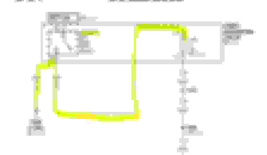
Awg, The reason I asked which one it was is because Im not 100% on what the difference between Relay Control and Relay Output is. (Diagram below)
Im assuming its the K51 18DB/YL in the C3 connection of the PCM. I know Ive back probed this guy before but I cant remember what the readings were. Ive been in so many different circuits that its all starting to blend together. Trying to take better notes to keep things straight. I jumped D4 to D8 last night and Fuse 21 and 18 powered up. Tried starting and nothing. I then jumped D2 to D6 and still nothing. Jumped bother circuits at the same time and nothing.
ASD relay:
D2 = battery. I get 12V
D4 = Ignition Switch, I get 12V
D8 = I can never get Fuse 21 and Fuse 18 to power on. I had my ignition on last night with the relay pulled and a test light on fuse 21. When I plugged the ASD Relay in, I can hear the relay click and see the test light blip on for just a sec. This tells me its trying to close but something is wrong. Could this be the signal from the PCM is getting disrupted? Ill test it out after work today.
My fuel pump runs for a few seconds when I turn the key to run. Not sure if its a full 3. I can smell fuel when I crank and I have pressure in the rail. Still dont have a pressure tester to see how much. Been busy finding this wire issue.
according to the FSM excerpt, the ASD control is the PCM provides a ground/earth to operate the relay,
however the PCM will not provide that path if it is unsatisfied by other conditions, such as the Crank Sensor
If I could establish the wire continuity between PCM and relay, and the terminal underneath is ok, I would be inclined to replace the crank sensor, as this is a common reason why they wont start
Clayzer, just going through your earlier posts ;
can you try one thing for me: bypass the NSS as trial. I know you mentioned it was OK but not sure how you tested that. Mine gave intermittent issues with no starts or no cranks and all my measurements showed it should not be the nss....and eventually it was. Got a nice multicomment thread in another forum on that diagnostic exercise I went through...
If you do resistance checks on the CPS, you can get a rough idea if its faulty (as in: if its out of spec you can assume it's faulty).
How do you bypass the NSS?
I�ve tried two Jeep CPS from working Jeeps and one from oriellys and they all show the same 5V reference, 12v signal, and 0-5v open and close signals.
I discovered my Dipstick G102 ground has no continuity to my negative terminal. Voltage pulses from .01-.180mv. I traced the BK and BK/TN ground wires to my ODB2 and they have similar readings. However In C100, BK has 8v while BK/TN has 9v (yes mt battery voltage is low). Where else does the G102 ground? Currently inspecting my harness for a bad wire.
Think this could be causing my P0122 and P1694 codes? I�ve heard bad grounds can cause sensors to have low voltages.