
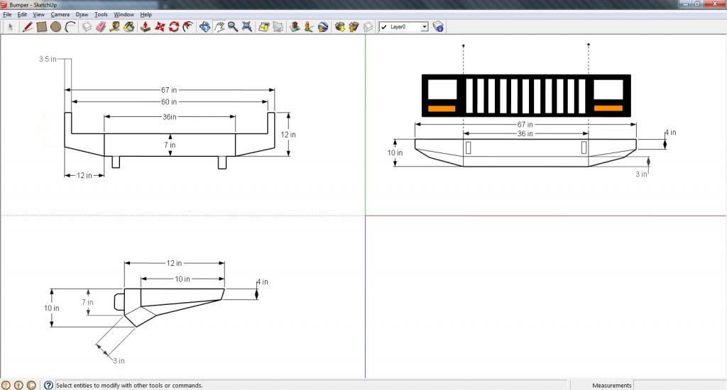
Well i'm just finishing up my welding classes at Dunwoody in MN. So in closing they want us to blueprint and make something to grade for a final project. Of course the first thing that came to find was a front bumper. I had always loved the JCR offroad bumper kit, so I drew this up.
The nice thing about this project, is that Dunwoody is covering the cost of metal. So its a free bumper! Pics to fellow as I progress.

The nice thing about this project, is that Dunwoody is covering the cost of metal. So its a free bumper! Pics to fellow as I progress.
Senior Member
Quote:
The nice thing about this project, is that Dunwoody is covering the cost of metal. So its a free bumper! Pics to fellow as I progress.
Originally Posted by Bilknutz
Well i'm just finishing up my welding classes at Dunwoody in MN. So in closing they want us to blueprint and make something to grade for a final project. Of course the first thing that came to find was a front bumper. I had always loved the JCR offroad bumper kit, so I drew this up.The nice thing about this project, is that Dunwoody is covering the cost of metal. So its a free bumper! Pics to fellow as I progress.
Is that the old version of sketchup or is that the paid one? Looks like a good start.
Quote:
Not sure what version it is, it was free, little tough to work with but helpful for drawing a draft.Originally Posted by blankdeluxe
Is that the old version of sketchup or is that the paid one? Looks like a good start.
CF Veteran
Are you planning on using a winch? Might as well make your mounts go past the steering box brace either way. And work your approach angle a bunch!

Member
With respect, the most obvious problem is that in the lower left hand corner picture, you are showing the skirt to be 3"....on an angle....with a total height of 10".
The square on the hypotanuse is equal to the sum of the yada, yada, yada..

The square on the hypotanuse is equal to the sum of the yada, yada, yada..
CF Veteran
Quote:
The square on the hypotanuse is equal to the sum of the yada, yada, yada..
You are correct, But. It is his upper right view that is a little off viewing it directly from the the font wouldnt be 3" up and down. It would like 2.5" or something depending on the angle.Originally Posted by Bruce in Montana
With respect, the most obvious problem is that in the lower left hand corner picture, you are showing the skirt to be 3"....on an angle....with a total height of 10".The square on the hypotanuse is equal to the sum of the yada, yada, yada..
SU doesnt take that long to draw. But when you do your views, draw it all to scale and then project your lines and everything should up. But as you can see your stuff doesnt really line up. (Yes I used paint, and no its not anywhere close to being exact but its close enough you can tell its off.)

Let me know if you have an other issues
-Zack
(coming from an architectural student)
CF Veteran
Quote:
its not an architectural drawing, it doesn't need to be a scaled drawing. thats what NTS meansOriginally Posted by Zacks98
But when you do your views, draw it all to scale
Quote:
it doesnt need to line up, its not an architectural drawing. its not even a weld drawing for that matter.Originally Posted by Zacks98
and then project your lines and everything should up. But as you can see your stuff doesnt really line up. (Yes I used paint, and no its not anywhere close to being exact but its close enough you can tell its off.)
its just something he sketched on a windows program.
Quote:
he's a welder, not an architect.Originally Posted by Zacks98
(coming from an architectural student)
mechanical/welding prints are a much different animal compared to the prints you read/draw...
CF Veteran
Quote:
it doesnt need to line up, its not an architectural drawing. its not even a weld drawing for that matter.
its just something he sketched on a windows program.
he's a welder, not an architect.
mechanical/welding prints are a much different animal compared to the prints you read/draw...
Hank,Originally Posted by hankthetank
its not an architectural drawing, it doesn't need to be a scaled drawing. thats what NTS meansit doesnt need to line up, its not an architectural drawing. its not even a weld drawing for that matter.
its just something he sketched on a windows program.
he's a welder, not an architect.
mechanical/welding prints are a much different animal compared to the prints you read/draw...
So where does it say NTS?
Maybe it had said Not To Scale wouldn't have confused Bruce?
"On a windows program"? You sir dont know what you are talking about. That is Google SketchUp, that is an ARCHITECTURAL program.
Welding prints are different, but mechanical drawings are pretty similar. Pretty sure a lot of them use that program called...um oh yeah CAD
Plus personally I would rather have someone else point out stuff I could do differently or a little better rather than my teacher. Let alone if they mark off points cause of it. Secondly if I was his teacher and saw that he did that and no one else did I might be will helping to help him more than everyone else.
My whole post was go give Bilknutz some advice and really talk to Bruce about it...kinda why I quoted him and not Bilknutz original post. And the only reason I said architectural student was because I know what Im talking about not blowing smoke out of my ***. No where in my post was I attacking Bilknutz or being a douche bag like you. So why do you take your tiny ***** syndrome some where else, unless you have some actually constructive information to add.
CF Veteran
 I almost worked to a degree in CAD, my school dropped half the programs I needed though. This is hilarious, it doesn't matter what he uses what program it is, what type of program etc. Hes trying to build it, let him build it.
 OP, mock it up with cardboard first so you can get the shape right, then transfer the pieces to metal.
CF Veteran
Quote:
So why do you take your tiny ***** syndrome some where else, unless you have some actually constructive information to add.
wow. totally uncalled for. i dont have tiny ***** syndrome. i have three years of formal education in print reading and drawing as a machinist/millwright...and over ten years of real world experience. take that how you like.Originally Posted by Zacks98
Hank,So why do you take your tiny ***** syndrome some where else, unless you have some actually constructive information to add.
all he was doing was "sketching" a drawing for his shop project, not building a house. i wasn't attacking you personally. leave the name calling for junior high.
and neither of us know exactly what the requirements for his drawing are anyways.
have a magical day.
CF Veteran
Quote:
That is Google SketchUp, that is an ARCHITECTURAL program.
...and mechanical, and civil. just sayin'Originally Posted by Zacks98
Hank,That is Google SketchUp, that is an ARCHITECTURAL program.
CF Veteran
Quote:
2X. Anxious to see how this thing turns out.Originally Posted by JerrytheJeep
OP, mock it up with cardboard first so you can get the shape right, then transfer the pieces to metal.
CF Veteran
Quote:
dish and take what?Originally Posted by Zacks98
Hank can dish it out but can't take it. Lol
Junior Member
Dang I thought this was about building a final project and it being free (being in welding school and building a front bumper and working on my rear bumper and tire swing, I know how big that is), not having a pissing contest. As long as he knows what he wants his measurements to be and uses cardboard to mock it up like suggested to make sure it looks exactly how he likes, who cares what his sketches look like or what program he used and what the program is "for".
OP- That is close to what I made and I am glad I used some cardboard to mock it up, cause it allowed me to see I needed to change a couple angles and what not. Good luck and I know you are goin to love it when it's done. Be carefull when you weld the mounting brackets on, not to warp them. Mine warped a lil and made it a B**** to totally mount up. Don't forget the two brackets in the front.
OP- That is close to what I made and I am glad I used some cardboard to mock it up, cause it allowed me to see I needed to change a couple angles and what not. Good luck and I know you are goin to love it when it's done. Be carefull when you weld the mounting brackets on, not to warp them. Mine warped a lil and made it a B**** to totally mount up. Don't forget the two brackets in the front.