When you click on links to various merchants on this site and make a purchase, this can result in this site earning a commission. Affiliate programs and affiliations include, but are not limited to, the eBay Partner Network.
Year: 1998 Classic (I'll get it running soon....) and 02 Grand
Model: Cherokee (XJ)
Engine: 4.0
The right way to install a manual switch for your e-fan
While I'm writing this up for the XJ crowd, the principles apply equally to other models that have an electric auxiliary fan.
I’ve seen a lot of posts about people wanting to install a manual switch for their e-fan, so they can turn it on whenever they want to, instead of waiting for it to come on automatically. Sometimes that’s because they want to get ahead of the heat (like when rock crawling) or simply because it’s not coming on automatically and they haven’t figured out why. (You should figure out why!)
I’ve also read posts about people getting a CEL (check engine light) when they use a manual switch with their e-fan. I’m not sure why this happens to some people (and not to others), but I have a hunch, and this method should avoid that problem. There are a lot of good ways to do this, but I think this is the best way for a number of reasons. I’ll explain why as I go.
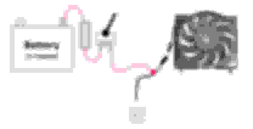
Let’s start by taking a look at the stock wiring. The Jeep fan is a simple DC motor, and all it requires to run is 12v and ground. That’s it. I won’t get into how and when the Jeep decides to turn on the e-fan – there are plenty of posts on that. We’ll just call that the standard Jeep fan controls. All we need to know is that the Jeep supplies 12v to the fan when it’s time to turn it on. Here’s what it looks like:
Notice that there is a connector plug near the e-fan. We’ll connect our switch on the control side of that connector, NOT on the fan side. Why? Well, if you have to replace the fan, do you want to have to re-do your connections? Or do you want to just swap out the fan and be on your way? (By the way, replacing that fan takes less than 10 minutes, start to finish, including getting out your tools and putting them away afterwards.)
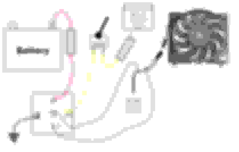
Now let’s look at how a lot of people install a switch. It’s pretty simple: just a switch, a fuse, and a power source.
This is simple, and it works. Don’t do it.
Why not? Well, remember that CEL problem some people have? Let’s talk about why that might be.
If you tap into the 12v supply line to the fan, and then turn on your switch, you get 12v into that wire that feeds the fan, and it travels to the fan and turns the motor. That’s what we want, right? Yes. But where else does it go? It goes back along that supply line to wherever it came from. We call that backfeeding voltage, and it’s not a good idea. I don’t know exactly where that voltage goes. Do you? I haven’t gotten into the wiring diagram to figure that out. It might be a relay somewhere (probably in the PDC), in which case, when the fan is NOT being turned on by the standard controls, it’s seeing an open switch, and it’s probably fine. No harm, no foul, no CEL. But what happens when the standard controls turn the fan on while you have your switch on? More backfeeding. Where does THAT go? You don’t know? Neither do I. I could figure it out, but I'd rather just do it right and not have to worry about it.
There’s another possibility. It might be going to a solid state switch in the PCM, in which case, well, we really don’t know what it’s doing. It might be okay, and it might NOT be okay. Solid state switches sometimes don’t like to have voltage showing up in unexpected places. When it comes to electronics, not knowing is not good. Unexpected behavior is usually unwanted behavior, and often, damaging behavior.
If you are one of those people who thinks (using the word, “thinks” very loosely here), “If I don’t know for sure that it’s bad, then it’s okay.”, well, go ahead and use the method shown above. It’s your Jeep, do what you want. But don’t be surprised if you are back here telling us about your CEL coming on whenever you switch on your fan, or about your PCM crapping out unexpectedly. There are good reasons that backfeeding voltage is considered a bad idea in the electronics industry. You don’t want unpredictability and that’s what you get with backfeeding.
Year: 1998 Classic (I'll get it running soon....) and 02 Grand
Model: Cherokee (XJ)
Engine: 4.0
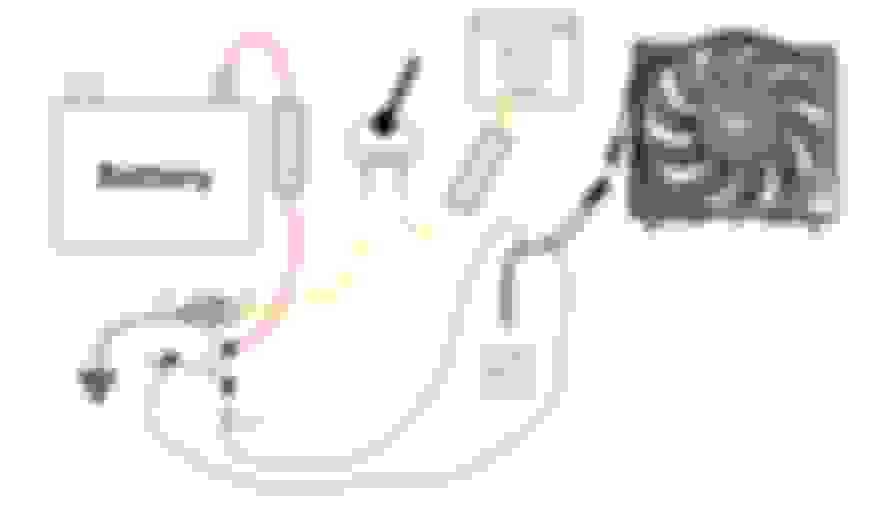
So let�s look at a better way that does not backfeed voltage into the existing fan controls. Instead of just tapping in to the existing supply line, we�ll interrupt it, and run it through a relay. Like this:
With this approach, the stock circuit is disconnected whenever your new switch is turned on. No backfeed. The heavy current wiring is kept in the engine compartment, too. You just need one smaller gauge wire (18 ga. is fine) running into the cab for your switch. You�ll supply the switch with 12v from the fuse box. The best approach is to find a source that is on only when the key is turned on. That way, when you shut off the key, your fan shuts off. If the source for the switch is hot all the time, you could accidentally leave your fan running and kill your battery. Either way works, and it�s your choice, of course, but think it through.
Now, let�s look at that diagram again and talk about what is happening.
First let�s look at terminals 85 and 86. When we turn the switch on, current flows through these two terminals to ground. In between is a coil. This coil forms an electromagnet, which operates the switch. This is how relays work. We use a small current to operate an electromagnet, which flips a switch which carries a large current. So, when your key is on, your fuse box connection supplies 12v to the switch, which connects it to the coil, which operates the relay. Now let�s look at the high-current side of the relay.
This relay has three terminals on the high-current side; 30, 87, and 87a. Normally, terminal 30 would be considered the �common� terminal, and is typically where you�d connect your power from the battery. If you wanted to use the relay to switch on some driving lights, for example, that�s what you�d do. We�re going to do things a little differently. No problem � the current doesn�t care what direction it flows through these terminals.
Terminals 87 and 87a are interesting. When there is no power to the coil, a spring keeps the switch connected to terminal 87a. We say that 87a is �normally closed�, abbreviated as �NC�. Terminal 87 is �normally open�, or �NO�. When the coil is energized (has current flowing through it), this is reversed. 87a is not connected, and 87 IS connected.
Understanding this behavior lets us do some interesting things with these common relays. We can choose different wiring combinations for different jobs. For our purposes, we�re going to isolate the standard Jeep controls from our new switch. We�ll do that by running battery power to terminal 87, which is normally open. We�ll connect the standard Jeep controls to terminal 87a, which is normally closed. Finally, we�ll connect the fan itself to terminal 30. How�s that all work?
When the switch is off, the coil is not energized, and terminal 87a is connected to terminal 30. That means that the standard Jeep controls are connected to the fan, just like normal. Switch off = normal fan operation.
When the switch is ON, the coil IS energized, and terminal 87a is DISconnected from terminal 30. That means that the standard Jeep controls are DISconnected from the fan. But now, terminal 87 is connected to terminal 30. That means that 12v from the battery is connected to the fan, which is what we want.
So, we�ve disconnected the stock wiring (preventing backfeed), and we�ve connected our fan to 12v. Thus, switch ON = 12v to fan, normal controls bypassed.
Year: 1998 Classic (I'll get it running soon....) and 02 Grand
Model: Cherokee (XJ)
Engine: 4.0
Now a couple of other matters:
Fuse sizes: I don�t know the current draw of the fan, but I�m using a 30 amp fuse, and it�s fine so far. That�s not good practice, though. I should look up the fuse size for the stock fuse, and use the same size.
The switch fuse should be small. A relay like this typically draws something like a quarter amp through the coil, so a 1 amp fuse should (theoretically) be fine. I suggest a 5 amp as they are easier to find, and a 1 amp might not stand up well to a car�s vibration. (They are pretty delicate.) Do NOT use a large fuse like a 20 or 30 amp. You want that fuse to blow easily if there�s a short.
Where to run the wires: for the battery supply, I connected to the terminal that supplies the PDC (Power Distribution Center, the fuse block under your hood near the battery.) Remember to disconnect the ground terminal of your battery before doing any electrical work! I used an inline fuse, butt spliced to 14 gauge wire, and run through split loom around the battery, up behind the fan shrouds, and over to the relay. I mounted the relay to the radiator support near the e-fan connector. (Sorry, no pics of the relay itself. L ) I didn�t do the math to size the wire � that�s seat of the pants overkill from many year�s experience installing automotive electronics. 16 gauge might be enough, but not smaller. 12 is getting ridiculous.
Here�s the connection to the PDC:
Anybody notice a problem here that needs attention? Send me a PM and I�ll tell you if you are correct.
By the way, I�m not a big fan of inline fuses, but I had it on hand. It would have been neater to mount a fuse block on the inner fender wall there, and use a standard ATC fuse, but I was pressed for time, and that would have meant another trip to town.
Year: 1998 Classic (I'll get it running soon....) and 02 Grand
Model: Cherokee (XJ)
Engine: 4.0
I unfastened the radiator shroud and the e-fan, and the split loom ran nicely behind them. I found good places to secure it with cable ties. Always use the black ones, folks. They last FAR longer than the white.
Then I just re-fastened the shroud and e-fan, and you can�t see the loom at all, except where it comes out to connect to the relay and PDC. DON�T just run a wire through here! The loom protects the wire from heat and mechanical damage and also gives a professional appearance.
By the way, those are decent crimpers. Don�t waste your time with the stamped metal jobs that come in a kit at the hardware store. A properly done crimp is every bit as good as a soldered connection, but you can�t do it properly without using decent tools. (If you think that�s a crazy thing to say, consider this: Crimped connections are used in aircraft and are mil-spec in many applications where soldered connections are not permitted. There are good reasons for that. Crimps get a bad rap because most people don�t know how to do them properly, use poor tools and connectors, and for NO other reason. People use pliers as crimpers and then say that crimp connections are junk. No, the operator�s brain is junk.)
I won�t go into how or where to mount your switch. There are lots of good possibilities and lots of individual preferences. You�ll figure it out.
There you have it, folks. How to install a switch for your e-fan, and a few lessons that can be applied to a lot of other little projects.
Year: 1998 Classic (I'll get it running soon....) and 02 Grand
Model: Cherokee (XJ)
Engine: 4.0
Originally Posted by BlueRidgeMark
When we turn the switch on, current flows through these two terminals to ground.
By the way, those of you who know the difference between hole flow and electron flow, please just shaddap. This is not the place for that. This is a tutorial for newbies, not a debate for experts, and not a place for you to show off your knowledge.