When you click on links to various merchants on this site and make a purchase, this can result in this site earning a commission. Affiliate programs and affiliations include, but are not limited to, the eBay Partner Network.
Thanks everyone! I'm super happy with Malcom now. It's been working so well I don't know what to do with my time! It's so weird not having a huge list of things to fix!
No new updates over here on Malcom. I've been getting caught up with work so much lately - we haven't even gotten out hiking much lately.
We are going out on some trips to the Rocky Mountains in the XJ in the summer to do hiking trail maintenance, so I need to build a to-do list to prepare for the road trips. I've updated my to-do list for the year below:
Under hood lighting
Install the two tweeters under the dash in the stock location
Replace valve cover gasket & paint valve cover.
Remove & paint the stock wheels - likely will do this in the winter when I change to winter tires
Cupholders - this is a good one to do while my wife is at school. I can take my time to fabricate these. I am also considering making a new, custom centre console lid to match.
Repair the rear hatch lock mechanism light switch - eg the thing that turns the cargo area light on when the hatch is open.
Replace the CAT
Replace the AUX fan with a new one - not needed until next summer
Fog lights
Roof rack - long term. Probably a year away at least.
Roof top tent - long term. Probably a year away at least.
Repair AC
Priorities:
Cupholders and custom centre console lid
Permanently wire the dash cam (using aux power plug right now. Not very nice and the aux power has too much of a voltage drop in the harness for the dash cam battery circuit to charge consistently).
"Easy" checks on the AC. Check relay and maybe bring into a shop for troubleshooting/ quote. I'd like to try to get the AC working before we drive up the mountains in the summer..
Check brakes and other routine maintenance.
Readjust the door gaps - I adjusted them a year ago but one door still has a small gap that I've been putting off.. because it's a pain to do on my own. It can be loud A.F. on the highway so I'd like to fix it...
Investigate roof top tents and build a plan for 2020
Does anyone have any recommendations on things to do before some longer road trips? We have two separate trips planned. On both trips we're going to be driving roughly 800-1000 kms each way and camping on the drive out there. The trips will be very similar to the one we went on when we first bought Malcom, so it'll be a nice comparison!
It's been a while...and that's not a bad thing. We've been using the Jeep a bit with no major issues. Finally took most of the tools out of the back, which is a huge step forward in having confidence in it!
I've been very busy - so we took it into a shop to do the brakes. The brake shoes were broken, some issues with the parking brake, and of course some brake lines busted while they were working on it so I'm pretty happy I didn't have to dig into it in the alley behind our apartment. So now the brakes are done, and should be ready for a long roadtrip.
Dash cam is permanently installed. I used a fuse tap, and there's no good place to install one so I had pulled one of the fuses out of the tap to get it to fit. I have a small fuse box that I'll be hooking up later this summer as an interior aux power (ignition switched) power source. This will be a more permanent solution. I just need time...
Installed some stickers. I must have gotten several horsepower out of it...
Roof top tents are off the list now. We'll likely be going ahead with a good ground tent. Our parking garage door doesn't have enough clearance and well, I'm getting sensitive to the fuel economy that we are getting since we want to go on longer trips.
I touched up some scratches in the paint.
I don't have much time before our first summer road trip, so this will be tricky to fit in but we'll see what I can get done:
Still need to make the custom cupholders. A road trip will be frustrating without good cupholders..
I should adjust door gaps before we get on the highway for days. Should help reduce road noise.
I snagged a cargo net from work; it's one from the back of one of our heavy duty trucks that we had to crush. I could have scored muuuuch more stuff but the cargo net was the most useful right away. I'll throw in some grommets and strap it in with cable.
I really dig those black stock jeep rims you went with. They also made those in white. I have never seen a cherokee with those stock rims before except on an old Jeep Cherokee ad (will see if I can find the picture).
I also think your lift turned out very nice and is exactly what I will be going for. 1.5-2" of lift. I am going to start a build thread tomorrow myself. Much like yours, mine will be slow going due to funds at times.
Do you have any plans to convert yours to a 4x4? Come on, you know you want too...
Good lord, here is the image of those rims but white or aluminum (hard to tell on the picture). You wouldn't believe the google hoops I had to jump through to find this image again......haha.
Haha. I'm glad you found the image after all that googling.
I've never seen the white rims. I have seen plenty of the black ones, like the ones I have, locally. I lucked out to find ones in such good condition.
It is a 4x4 We usually drive it in 2WD, but change it over to 4WD part time or full time when going through unmaintained access roads. Just this past week we drove up to the Rockies around the Crowsnest Pass in BC/ Alberta. Drove up some access roads, which were not too bad, but had to drive up a 4x4 road to get closer to the camp we were volunteering at. Then had to have gear driven in on ATVs and hike the rest. The XJ handled that like a pro. My wife (who owns the Jeep and drives it) was having a blast in the mud!
On other notes - on our drive out to Alberta last week, we had the alternator die like 45 kms outside of Calgary.. at 12:15am. Didn't see the battery voltage drop on the dash since, well, when the battery voltage gets low one of the instrument panel lights doesn't work so we couldn't see the voltage gauge in the dark. So we had to wait ~ 2 hours for a tow and got to our hotel at around 3am. The alternator drew the battery down quite low and killed the 4 year old battery, so a new battery and alternator was needed. Took 2.5 days to get the work done and parts in (the shop was not open Sundays) but we got back on the road with only slightly lighter wallets.
Then as luck has it, on our way back home the compass/ temperature display died. I took it apart and noticed a couple blown capacitors. The repair looks simple. I'll post later once I start fixing it. It's a minor issue but we like the temperature sensor, and honestly repairing it will cost dollars (each cap is like $0.50 each) so I'll just bite the bullet and do the repair hopefully this weekend (if I can find any capacitors locally).
But since the images on the thread above no longer show up, it has taken a little more work to understand the instructions than it should have.
I tested a bunch of the PCB traces today and ordered new capacitors from Mouser as well as a new crystal, just in case.
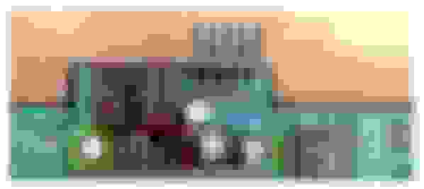
The board doesn't look too fried - damage is local to the capacitors. From my tests today, the traces are in tact and not shorted or open.
The board / traces around the capacitors. The ceramic capacitors with red circles have open circuit, and the one with the green circles seems intact and shows continuity across it. I will be replacing all three. The larger capacitors are almost all dead and will need replacement.
Once I get the new components in the mail, I'll repair the board and test it out. I'll update the post if the repair works and I will attach detailed description of what I did.
Last edited by moonsandals; Jun 30, 2019 at 11:14 PM.
As per my last post, the overhead console computer died on us on our way back from Alberta.
I followed the NAXJA post on how to repair the overhead console computer, but since the images were no longer on the post it took me a little more effort to interpret the instructions. Full credit goes to the OP on NAXJA - I only had to interpret the instructions without the images.
My instructions will quote the original NAXJA instructions, but I add my interpretation and how I implemented it.
The Problem
From what I understand from the NAXJ post, the capacitors around the 5 Volt regulator blow and take out PCB traces with them. On top of the capacitors themselves blowing, this can short or open traces on the PCB.
First, the area that typically gets fried sits around a 5volt regulator which is highlighted with a white arrow in the picture below. From what I am seeing, the cause of failure always seems to be one (or all) of the electrolytic capacitors highlighted in the blue boxes. This makes sense because electrolytic capacitors tend to last a LONG time but what can kill them is heat and sitting next to the roof of an XJ for 20 years is a pretty sure way to accelerate their demise. The problem is that when they blow, they take other components (and traces) with them. The 3 small ceramic capacitor to the right of the voltage regulator (numbered 1-3 in orange)are prime targets for this. …
Before we start, I am going to point out the voltage regulator since the original images are lost. The yellow box below is the voltage regulator; L487. The NAXJ forum posts recommend upgrading to an L4947 since it works the same but runs much cooler (so is less likely to overheat the board and cause failures). I have not read through the post and datasheet in enough detail to understand if any modifications to the circuit would be necessary to support the L4947.
The red box is a display driver.
The purple box is the CPU.
You can find the datasheet on the internet quite easily for the power module. The pinout is shown below.
From the top, the pinout should be as follows:
From the bottom, the pinout should be as follows:
These things apparently get very hot. When mine failed I could feel the heat coming off of the board off of the other voltage regulator on the left (L4812CV). I was touching the plastic overhead console above the on/off button and was scared I might burn my hand – it was that hot.
Failed Components
As described above, a number of capacitors seem to fail. The larger electrolytic capacitors (in yellow boxes) seem to fail and cause the smaller ceramic SMD (surface mount) capacitors (in the red box) to fail. It is not clear to me if the other, blue, electrolytic capacitor is also prone to failure but it’s probably worth checking and replacing if necessary at the same time.
I also understand that sometimes the crystal (the blue thing in my board, in the purple box) can sometimes fail. If you read through the NAXJA thread he recommends replacing the crystal and has some comments on compatibility of the replacement.
Power Circuit
The real issue is that when the electrolytic capacitor blows, these little caps get really hot and often cause some of the traces to break. The one highlighted in red is often bad and this one is very important since it is what provides the ground signal to two of the electrolytic capacitors. To test this, turn the board over and connect a mult-imeter (set to ohms) between pin 3 of the regulator and the negative pole of each capacitor (marked with the white bar and a "-" sign on the sides of the capacitors). When you connect your meter to these points, each should read close to 0 ohms.
So what we are looking for is continuity, or low resistance, between pin 3 and the negative side of the large capacitors. The large capacitors are marked with a white stripe on the negative side, so from the bottom of the board I have circled the positive pins below in yellow
For me, this tested OK. The resistance was very low and continuity checks were good. No issue with the power circuit on my board so I did not take this any further.
Some more information on the power circuit from NAXJA is quoted below – in particular this is where the OP talks about upgrading to the newer power module.
It is the same function as the L487 you have now but runs MUCH cooler!
What the datasheet describes is that the "reset" function supervises the output (on pin 5) and then charges up a 100nF capacitor (one of the tiny surface mount ones on the board) on pin 4 (to ground) to create a small delay. Once the cap is charged (microseconds), you should have 4.5V-5V of power on pin 2 of the regulator. If this isn't happening, you need to check two things:
1) the 100uF capacitor (sits in the middle of the three 100uF capacitors) is directly wired to pin 5. If not, the voltage on the regulator won't stabilize and pin 2 will never get energized. BTW, it goes without saying that you need to make sure that the capacitor is still good and that the negative side still connects to ground (the ground connection is one of the traces that frys so you need to double check it)
2) there is a small surface mount 100nF (0.1uF) capacitor that sits between pin 4 and ground. This can sometimes fry due to heat and if so, the pin will never charge and the board will never light. If you have a good meter that can check capacitance, you can try to check it but they are VERY cheap ($3.00 will buy you 100 of them) so I usually just change them out or (if the board is burned in this area), I switch to a ceramic "through-hole" capacitor and solder it on the backside of the board between pin 4 and ground.
Same offer as my earlier post - if you are still having trouble, send me a PM with your email address and I will send you some pics and further guidance.
Also note, as per my earlier post, you can "kinda" work around this by soldering a wire between pin 5 (5V out) and Pin 2 (reset out) on the regulator but I don't recommend this because it makes it impossible for the CPU to reset itself if it gets confused. Having said this, it has the effect of removing the reset function from the equation and the board should start up. I often do this when I start working on a board just to figure out what I am dealing with but I always complete the repair properly to avoid other issues.
Again, I wasn’t about to go down this rabbit hole since I had no power module issues and I couldn’t find this power module on Mouser Canada. So I just hoped that the existing power module continues to work as designed, and that after I replace the burned out components the rest of the board can last another 10+ years on top of the 28 years the Jeep has been in existence.
CPU Reset Circuit
The other trace that tends to get burned up is the one that connects pin 2 of the regulator to the CPU. This pin provides a 4.6-4.7v reset signal to the CPU and if it is broken, the CPU won't turn on. The best way to check this trace is to use your multi-meter again (still on the ohms setting) between pin 2 of the regulator and pin 5 of the CPU (both ends highlighted with the yellow arrow). When you connect to these you should also get a reading of close to 0 ohms.
I could not find the CPU datasheet to confirm where the Pin 5 of the CPU. However, based on the description I realize that the two solder dots circled in yellow below correspond to the description of Pin 5. So I measured Pin 2 of the power module to the rightmost solder dot (assuming it was Pin 5 of the CPU).
For me, there was very low resistance so I did not need to repair this trace. However, since the trace is very stained closer to the burned out capacitors I decided to add a wire to jump it anyways.
Also Recommended in the NAXJA Post:
The NAXJA post also recommends to check the following:
1) the trace that connects the CPU to the display chip runs through the "hot zone" and often breaks. You can easily check it from the backside with a meter by testing the the points where I have connected the blue wire. If you measure an open circuit, this needs to be repaired and I recommend using the jumper wire at the link below (insulation can handle high temps)
I checked this on my board and it was fine.
2) the trace that connects the 220uF capacitor to the display chip is also in this area and can break. Test by connecting your multi-meter between the second set of points below and repair as necessary.
I checked this on my board and it was fine.
The Fix
Capacitor Replacement
If both of your multi-meter tests are good, you should be able to simply replace these three capacitors. All 3 are 100uF 35V capacitors and are available online or from places like Fry's Electronics. Typical cost is ~$1.50 each (3 needed).
The NAXJA thread had some recommended a few different capacitors – at first through a Radio Shack link that no longer works for me, then some high temperature capacitors via Mouser that also no longer worked for me. I did my own search on Mouser and found some high hour, high temperature ones instead of his recommendation.
You can search for your own as long as the specs match (capacitance/ voltage/ type/ pin spacing) and try to keep them high temperature and make sure the diameter and length actually fit on the board.
For this replacement I started with a photo of the board to make sure I had the polarity of the capacitors documented so I could install the new ones in the correct orientation. Again, white stripe is negative of the capacitor so I ensured that I remembered that the negative pin was closest to the display just so I wouldn’t make a silly mistake.
I don’t have a third hand, so I needed to jig something up to work on the board. I used quick clamps. I don’t recommend this. It’s difficult to grab the board anywhere not on a component, and I found the board sometimes would try to bend a bit…
So using this setup, I de-soldered the capacitors from the back and gently pulled them off the board using a pair of needle nose vise grips. I used the vise grips to apply constant pressure on the capacitors so I didn’t have to focus on the soldering iron, squeezing pliers, and pulling at the same time. I just found it easier. The solder cools quickly so I just gently worked one pin at a time and alternated quickly between them and “inched” each capacitor out.
Below the caps you could see some damage, some electrolytic fluid, possibly some flux, and some grime.
As you can see I kept the dark blue capacitor on – it was not burned out and I forgot to buy a replacement. I’m really annoyed with myself for forgetting because replacement would have been dollars and only about 10 minutes of my time at this point.
Next, I removed the SMD capacitors. To do this I just used the tip of a hot soldering iron to warm up each pad, which de-soldered it from the board. Then as I was doing that I applied a little pressure to “push” the capacitors off the board. Each pad of the SMD capacitors easily came off the PCB as they were de-soldered, and the ceramics of the capacitors broke very easily by doing this so the whole thing just broke into pieces and more or less fell off the PCB. I was really relieved by this – I’ve heard stories of damaging PCBs when trying to remove SMD components.
I then cleaned the board with rubbing alcohol and a Q tip.
I then soldered the new electrolytic capacitors on. I just heated the solder on the board in each hole again using my soldering iron and just gently pushed the capacitors through until they were fully seated on the board. I had to be careful because the new capacitors are a little larger than the original ones and take up a little more room so I needed to make sure they all fit nicely with clearance to keep them cool.
I had to add a little more solder to give them a good connection, as most of the existing solder was removed, but that’s expected.
I then cut the pins down – I wanted to make sure the pins being used for the next steps are kept long enough to give me something to solder to.
And that’s it for replacing the capacitors.
Power Circuit fix
The solution on the NAXJA forum post is summarized below, but since I did not have an issue with the power circuit I did not go into this in any detail. So if you have issues with your power circuit you will need to do your own research and review the NAXJA post yourself.
If you found a broken trace between pin 3 and the negative poles of the electrolytic capacitors, the easiest fix is to turn the board over and solder a wire between pin 3 (ground) of the regulator and the negative pole on one of the new electrolytic capacitors. This essentially re-attaches the connection I highlighted with the red line in the pic. Here is an easy trick: rather than looking for small wire, simply use some of the excess wire you will cut off the bottom of the capacitors and slide some heat shrink tubing over it. This will insulate the wire to keep it from touching any other part of the circuit.
CPU Reset Circuit fix
Again, the instructions are below from NAXJA but I had to do a little more interpretation without the photos so my implementation is also shown below.
If you found a broken trace when you checked the connection between pin 2 of the regulator and pin 5 of the CPU, the fix is a little harder. The break is usually on a small trace that runs right between the orange 2 and 3 in the pic. If you look closely at the pic, there is a small solder spot directly under the orange number 3. What this hole does is connect the trace on the top of the board to another trace on the bottom of the board. If you connect your multi-meter between this solder blob and pin 5 of the CPU, it should read 0 ohms and if so, I typically turn the board over, heat up this blob and feed a small wire through it. I then attach the other end of the wire to pin 2 of the regulator (using heat shrink insulator again).
I did this repair just to be safe since the trace had some damage. The materials I found that could be used are below, but I did not order this because I already had single strand wire on hand.
I did this repair last – so you can see below a lot of the other fixes along with it. This is the long purple wire going from Pin 2 to the solder dot on the board I identified above. Soldering to the solder dot is easy – heat up the dot and it becomes fluid – and push the wire through.
Burned up ceramic capacitor fix
The NAXJA post discussed whether these are necessary or not in a few places. Although the quote below states they are not necessary, I think the conclusion was that they are important for filtering the power signal. I could be wrong, but I decided to replace them.
This fix isn't really necessary since the board will work perfectly without these capacitors but if anyone wants to change them out, they are all 100nF and can be replaced on the backside of the board with traditional ceramic capacitors. These cap's are simply used to try to protect the voltage regulator when something goes wrong. I have numbered them in the pic and the connect as follows:…
For these I bought ceramic capacitors from Mouser as below. These need to be installed from the back side of the board – they are not surface mount.
Capacitor #1
Connects between pin 2 of the regulator and the positive side (opposite of the side marked with the white bar and "-" sign) of the middle electrolytic capacitor.
Capacitor #2
Connects between pin 2 and pin 3 of the regulator
Capacitor #3
Connects between pin 3 of the regulator and the positive side (opposite of the side marked with the white bar and "-" sign) of the right-most electrolytic capacitor.
So connect pin 3 and the circled pin with a ceramic capacitor.
I didn’t take photos of each step, but it should be self evident. I used heat shrink tubing over the bare leads of the capacitors and I also used wire to extend some of the connections from capacitor to the pins. The heat shrink tubing is just a little loose – it’s not the right size – but I was also sealing the ends with liquid electrical tape so I used that to retain the shrink tubing as well.
The key in this step was to make sure I left enough space for the plastic housing – there is about 5-8 mm (I don’t know for sure – I didn’t measure) between the board and the plastic housing so you can fit the capacitors with some room, but not too much. I kept test fitting and one time I needed to re-heat a connection and reposition a capacitor to be sure it fit. This can get tricky with so many parts soldered off of the same pins as a terminal.
Clock issues.
The NAXJA post suggested a new crystal. I did not think I had an issue with my crystal, but bought one just to be safe.
I am finding that the later rev's of the board use a different clock as shown in the pics below. The newer ones (blue in the pic) fail VERY easily so I recommend replacing them with a standard 4MHz crystal as I have done in the second pic below.
Note: the old crystal has three pins while the new one only has two but don't worry about it, just connect the new one to the two outer holes and leave the center one (ground as Karsten noted earlier) disconnected.
The new Crystal is available at the link below:
The crystal I purchased is this one. I am pretty sure this is the one recommended on NAXJA.
I ordered the below parts. I ordered more than I needed as spares since each part is so cheap (shipping was more expensive). In some cases (such as the wire) I did not order any although I had it sourced because I had wire already on hand.
Result:
So, after all that my board works. We tested it by just switching on the ignition switch and the display works and both the temperature and compass direction are shown. I need to calibrate the compass so we will see how that works.
Last edited by moonsandals; Jul 7, 2019 at 02:54 PM.
Just posting some plans for interior aux power wiring that I have.
I had wired up our dashcam "permanently" last spring using the supplied "add a fuse", and the only circuit that I knew had enough current was the clock circuit (10A).
I wired this up but realized that the add a fuse didn't fit, so I had to remove one fuse which disabled the clock circuit (which I had repurposed to USB ports for the back seat).
I don't like this, and was concerned that using the add a fuse would strain this circuit even if I got it to fit properly so I was planning on adding an auxiliary power fuse box under the dash for additional accessories. This way I'll have something to expand within easily if I add stuff to the interior later (more charging ports, backup cam, rear entertainment for future kids, etc). There are six spots open on the fuse block so I think there'll be plenty of room to expand within. I'll probably wire with something rated for more than 30A, but the in line fuse I have and the relay is designed for 30 A so I'll keep it at around there for now. The fuse block is ~ 100 A max. I think I'll struggle to use 30 A though...
I want to keep the clock circuit in tact and be able to rip it out if I sell the Jeep or redo the entire thing. This also makes it MUCH easier to wire since I have to do the work in our alley behind our apartment. The more modular it is, the easier it is for me to wire in. So I came up with the below scheme:
Use a Fuse Socket Connector to tap into the clock circuit (
Use the relay to switch a fresh power line from the battery on
Connect the new (relay switched; ignition switched) power source to a new smaller fuse box that I put under the dash
Use this fuse box to run the dashcam, USB ports, other accessories
The diagram I put together is below.
The yellow box is the Fuse Socket Connector. See the link above. Basically it just jumps each lead on the fuse directly.
Thoughts? Am I out to lunch?
I'm planning on wiring this up in my apartment (on the table) this week if I can then install into the Jeep one day on a weekend (either next weekend or the weekend after).
We had been having issues with starting the Jeep this past winter. Turns out, oil change was overdue so we did that a few weeks ago and it made it start and run smoother (facepalm). However when I did the oil change I also noticed a dead headlight high beam relay from my headlight conversion. That would explain the random battery drain / weak battery we had a few times that was throwing me for a loop.
Then last weekend our high beams stuck on (my wife tried flashing them at another driver and forgot the relay was dead). Thankfully we noticed before parking at a trail head otherwise we would have had a dead battery again.... It was definitely a blown relay. Unplugged the relay and problem solved..for that afternoon anyways.
I ordered three Bosch 0332209150 Relays from Amazon to replace the cheap relays that came with.
Then this past Saturday, my wife had to drive to work. I had no idea she needed the car and I was planning on replacing the relays at home while she was at work. She needed to work late and was concerned about not having headlights. Even with highbeams disconnected, the headlights had been flaking out on her and the other relay may have been on its way out. The new relays were still at the post office so I let her drive to work (a special event she was attending with her students) in the morning, I picked up relays from post office when that opened and took the bus to meet her. I then swapped the relays in the parking lot.. narrowly avoiding the wrath of a security guard.
Then I stuck around to watch the event and when she was done work got a ride home. New relays work well. But man that burned a day to make her comfortable and happy. Really easy to switch out (20 mins total, mostly because the relays are in a tight spot next to the battery) but I spent the whole day out to do it instead of working on other projects.
Ive got a spare relay in the tool kit in the back now.
Been slow, and with COVID19 closing all our usual hiking and camping spots we haven't been out that much. Entire communities are closed to outsiders in our area. Some stuff is opening back up in the coming weeks so maybe we will get out a bit more.
Funds have been tight. We renovated our home last fall and are now expecting a child in October. I'm also working 80% now due to COVID19. So a 20% hit on my salary.
So I've been trying to do low cost, high effort projects. The Jeep doesn't get priority (getting ready for the baby does!) but I can squeeze some work in.
My to do list has shuffled around a bit.
High priority - low cost:
Cupholders - making custom ones now. I hope to post finished photos next week.
Center console lid - also planning to make a custom one with storage integrated. Maybe end of summer.
Cargo net install
Baby car seat install and install a car seat tether anchor if I can find a stock one from the recalls
Readjust the door gaps
high priority - high cost
Repair AC
Entertainment center - stereo, screen, etc for kid.
New rocker panels/steel tubing. - ours had been a bit rusty when I bought the Jeep and "temporarily" repaired them with fiberglass. It's been years. I should do this. There is a local shop I'd like to have install steel tubing but it'll be expensive. It's be nice to do myself but no space or tools.
Low priority - try to get done
Valve cover gasket - very small leak. Not a problem but would be nice to do and paint valve cover
New aux fan - cooling is not a problem but this fan should be better.
Under hood lights
Low priority - maybe never
Paint wheels to colour match Jeep
Center caps for wheels
So no updates. Boring I know but I'll have some photos in a week or two of the cupholders and maybe the cargo net.
I've been really rethinking how we store stuff in the back. Maybe a redo of organization in the back is needed.
Last edited by moonsandals; May 10, 2020 at 12:55 PM.
Car seat is installed. It doesn't need a tether yet, and I can't find a tether attachment that fits my year XJ. I've been through all of the recalls and contacted the dealer in my area but they can't find the parts. They are out of manufacture and my dealer can't find one. There are other options but they aren't official so if I add one it wont be by the book.
Regardless the car seat changes the look quite a bit haha. And it'll be different going on road trips - I'll need some way to make stuff accessible since I usually put stuff in the middle of the rear bench so I can grab it easily.
We also added window shades which are just nice regardless. Been meaning for an excuse to get some. Jolly Jumpers
Parks are open again and we got some reservations. So we are scrambling to get summer tires on and get it serviced. Brakes need to be looked at and summer tires installed. Rather than do this myself in the alley, the trusty shop around the corner will do it pretty cheap and will look into the air conditioner at the same time. So hopefully he can figure out the air con for cheap and get that running this summer.
I've loaded the tires in the back several times and for some reason we never figured this out. It fits so nice! We normally lay them flat..
The cupholder didn't get done in the past two weeks due to weather and me having to buy something. I've got everything I need now so I'm certain I'll be done this Friday. I'll post photos.
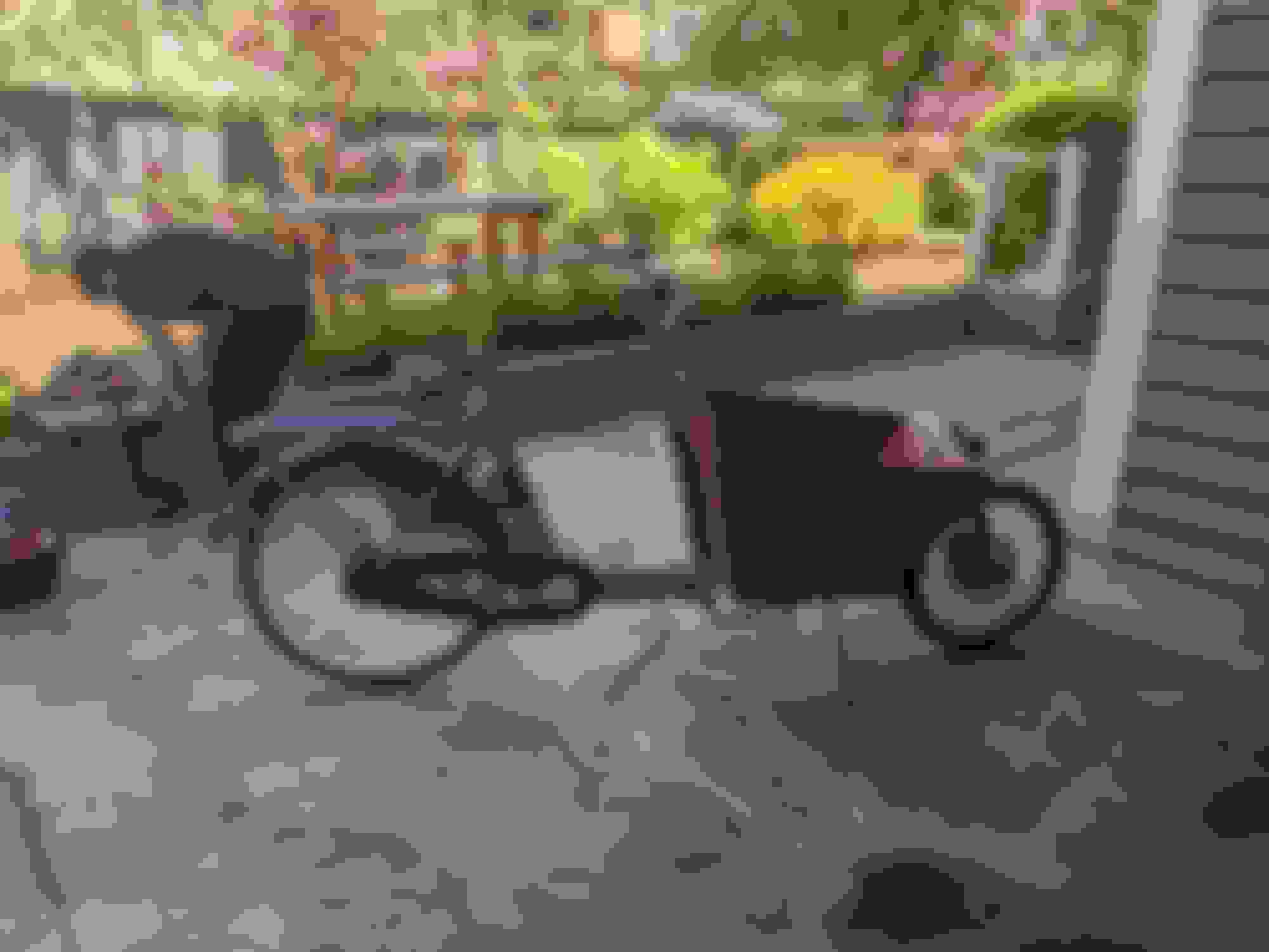
Also bought a cargo bike to carry the little one around the city in! Not a Jeep but still very cool and had taken a bunch of my time lately (and will take my time again this weekend).
Car seat is installed. It doesn't need a tether yet, and I can't find a tether attachment that fits my year XJ. I've been through all of the recalls and contacted the dealer in my area but they can't find the parts. They are out of manufacture and my dealer can't find one.
I think I have seen what you need on Ebay a couple times in the past over the years.
Very infrequently and for more money they I figure they are worth.
But I guess if they are that rare.
None recently though.
I think I have seen what you need on Ebay a couple times in the past over the years.
Very infrequently and for more money they I figure they are worth.
But I guess if they are that rare.
None recently though.
Thanks. I used to see them often, but came up dry when I actually need one. It figures.
Our local scrapyard also has closed down..news to me.
I guess I will keep an eye on eBay. It would be insane to spend much on it though.
Thanks. I used to see them often, but came up dry when I actually need one. It figures.
Our local scrapyard also has closed down..news to me.
I guess I will keep an eye on eBay. It would be insane to spend much on it though.
It was awhile back but I want to say the last time I saw some the Ebay seller had 3.
And I am just assuming these were the car seat tie downs you are talking about.
I vaguely remember a $60 price tag and that could have been for 1 not all 3.
I was just about to try and find the part number, cause I stalk Ebay pretty good, and if I
found some would PM you.
Well I am going to send you a PM after I post this.
The Jeep is at the shop. They are doing the front brakes and checking the AC. For AC, first making sure the parts actually work electrically, then if there is no charge they may need to retrofit and upgrade from R12 to R134a. May be $$ but it's so frickin hot out and the road to the trail we are working on this year is intensely hot and exposed so this will be important. My wife drives and will be 6+ months pregnant when we go on our trail building trip this year. She must be comfortable.
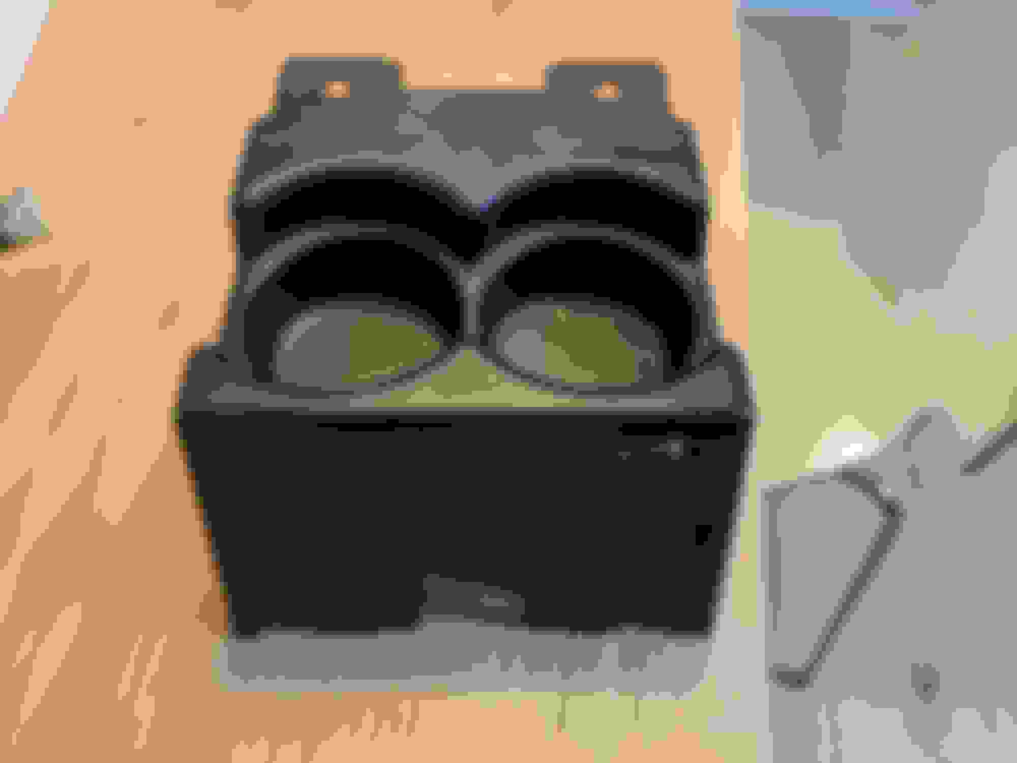
I finished the cup holders, more or less. I need to wait for the paint to fully cure overnight before assembling with screws. And the Jeep is at the shop so I can't install yet. You should get the idea though.
Original cupholders suck. I can't even fit my travel mug or a bottle of pop in them.
So I took some cardboard for templates, scrap balsa and foam and made a replica, but this time with a buldge on the sides do I can fit some large boat cupholders I bought on Amazon.
The only thing I bought was the cupholders from Amazon. The rest of the structure, balsa, foam, plaster, fabric, resin, Bondo, paint were all already in my storage. The resin and Bondo was old and annoying to work with and was tossed after this. I pretty much used them up, and the little bit left won't be any good for any future projects.
So the total cost of this was around the same amount it would cost to just buy a replacement stock one from Crown.
Foam and balsa, in progress.
Smooth out with plaster.
I wrapped it in cotton and used polyester resin to give it structure. The photo won't upload for some reason though.
Then Bondo and glazing putty.
Then paint.
I meant to use textured paint but I only had ceramic engine paint and I wasn't sure if it would cure nicely without baking it. So I stuck with black gloss.
I might pull it out later and repaint with textured paint later. This is good enough now.
And I'll install in the Jeep when I get it back.
The boat cupholders are HUGE and now I need to get something to keep my mug from flopping around. But I have a solution for that up my sleeve.
AC repaired and upgraded to R134a. Surprisingly low cost despite several new parts (drier, valves, fittings, seals), conversion kit and flush. We are cautiously optimistic. The whole system was vacuum tested and no leaks. And then filled and checked over several days for leaks and it's holding. So we will see if it holds up or if we need to replace more parts (hoses, etc) and refill. But it blows cold air!
Front brakes replaced (did the rear brakes and brake lines last year)
Summer tires and wheels mounted (just an excuse to have our mechanic look the car over)
Brake light switch replaced since it apparently was sticking on. I guess my wife had the right "feel" for it to avoid it sticking on normally but I have been suspicious for a while and I am paranoid and check the tail lights every time we stop to make sure they work haha.
I also installed the cupholders. Fit nicely!
I changed the bolts to a different size after taking this photo. M6 bolts don't fit but M5 bolts do.
The little "nubs" on the front look a bit funny but they are comfy to rest your arm on the top of.
Next up is a center console lid with some organization built in.