
Questions for KENCC - instrument cluster


Thread Starter
Senior Member
Joined: Jan 2017
Posts: 799
Likes: 4
From: usa
Year: 2000
Model: Cherokee
Engine: 6 cylinder
Caution long!
First of all Ken , thanks again for posting those connector pin outs. Was a real eye opener for me. Assumed the gauges were hard wired to their sensors, etc. Some of us are here to learn what we don't know, myself included.
Now for the questions if you would.
Only been here a short while but noticed a lot of xj instrument cluster issues. Most apparently go away on their own suggesting intermittent something or others.
Lacking a detailed schematic of the cluster:
1. I know zilch regarding the data bus which energizes the gauges. I assume its a digital bus maybe pcm but don't know its base frequency?
If its a high enough frequency, i'd think the cabling to the cluster connector needs to be coax to minimize emi interference primarily from ignition voltage glitches.
Or is it just plain old single conductor copper wire?
On the other hand the data protocol could be current loop pcm?
Can you elaborate on this?
2. Most cluster anomalies appear to pertain to the voltage gauge.
Why does the voltage gauge malfunction while the other gauges appear to be OK?
Since the bus is a digital protocol, there needs to be D/A Converters (DAC) involved for the analog gauges to work properly.
Could it be if the cluster looses ground, bus or B+ momentarily via the connectors, the output voltage of the DACs are still there maybe by capacitors to keep the gauges apparently reading correctly for a short time?
Are all the gauges serviced by the bus equally or is the voltage gauge serviced more often than the other gauges?
3. What triggers the 'Check Gauges' alert?
Is there internally in the cluster a watch dog timer (WDT) monitoring the data bus for activity?
Loosing ground, B+ or the data bus temporarily could trigger the WDT to indicate the fault.
I'd appreciate any info you or any one else has regarding the data bus.
CF Veteran
Joined: Aug 2010
Posts: 8,357
Likes: 103
From: Canton, MI
Year: 1999
Model: Cherokee
Engine: 4.0
A lot of ground to cover in your questions. The best I can do is to provide data that you can read/look at in order to understand the CCD Data Bus system and the instrument cluster functions.
First, here's some links to discussions about the CCD Data Bus.
CCD Data Bus Info (some info goes beyond the XJ) The Bias Module in our XJ's is in the Instrument Cluster
http://www.cnblogs.com/shangdawei/p/3570499.html
https://mopar1973man.com/cummins/articles.html/24-valve-2nd-generation_50/51_engine/electrical/ccd-chrysler-collision-detection-data-bus-r329/
http://www.autonerdz.com/yabbfiles/Attachments/dcx_network_ppt.pdf
SCI Info (limited use in the XJ)
http://www.tuicool.com/articles/NNZnInI
Network Standards
http://www.avt-hq.com/brief_slides.pdf
Next, here's my summary of the CCD Data Bus:

.

.
Next, here's some diagrams pertaining to the CCD Data Bus:

.
SCI circuits

.
Instrument Cluster interface

.

.
Instrument Cluster description - how the gauges work

.
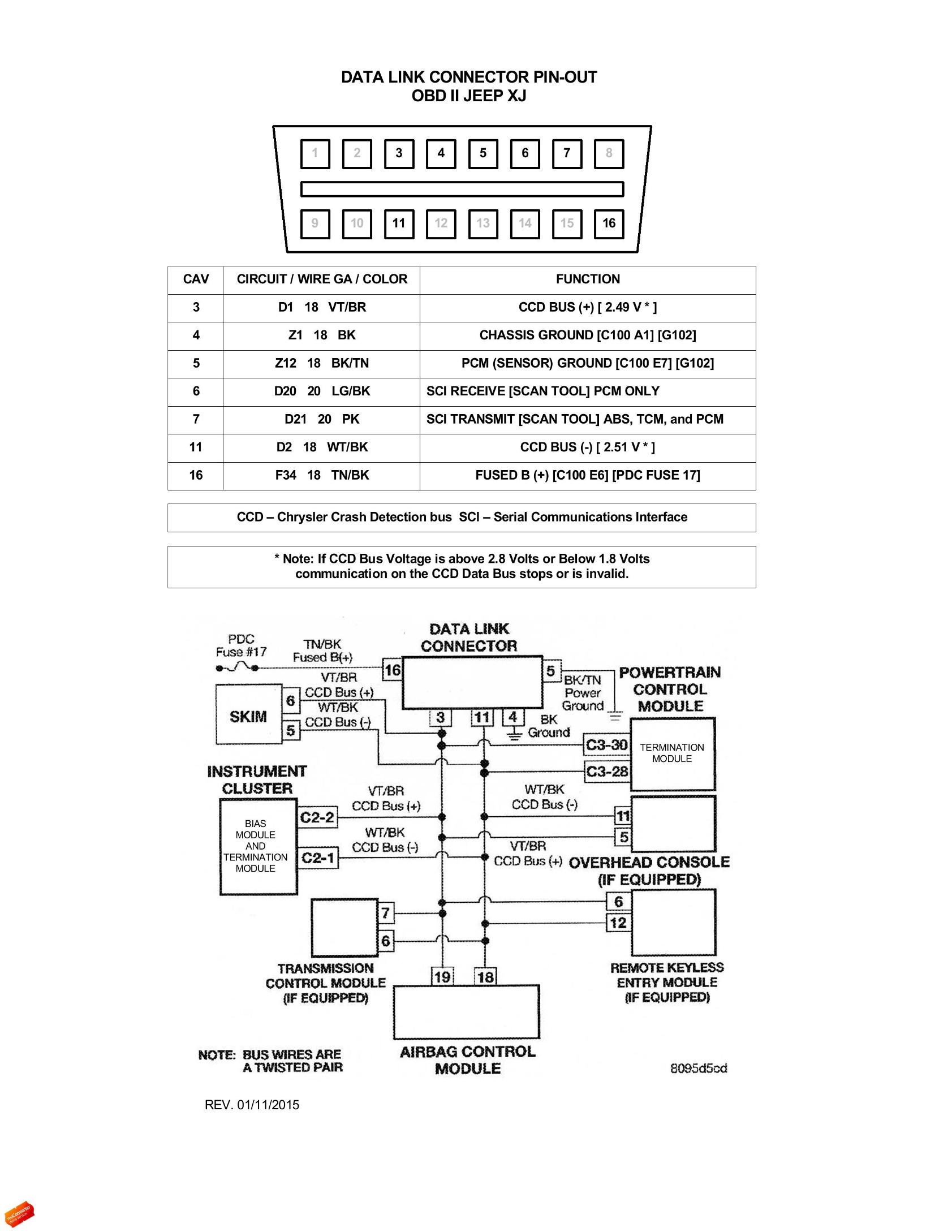
CCD Bus testing at the DLC, with the DLC pinout and Modules on the Bus.
.
Power source for the Instrument Cluster

.
Hope this helps.
First, here's some links to discussions about the CCD Data Bus.
CCD Data Bus Info (some info goes beyond the XJ) The Bias Module in our XJ's is in the Instrument Cluster
http://www.cnblogs.com/shangdawei/p/3570499.html
https://mopar1973man.com/cummins/articles.html/24-valve-2nd-generation_50/51_engine/electrical/ccd-chrysler-collision-detection-data-bus-r329/
http://www.autonerdz.com/yabbfiles/Attachments/dcx_network_ppt.pdf
SCI Info (limited use in the XJ)
http://www.tuicool.com/articles/NNZnInI
Network Standards
http://www.avt-hq.com/brief_slides.pdf
Next, here's my summary of the CCD Data Bus:
.
.
Next, here's some diagrams pertaining to the CCD Data Bus:
.
SCI circuits
.
Instrument Cluster interface
.
.
Instrument Cluster description - how the gauges work
.
CCD Bus testing at the DLC, with the DLC pinout and Modules on the Bus.
.
Power source for the Instrument Cluster
.
Hope this helps.
Last edited by CCKen; Jan 16, 2017 at 08:48 AM.
Thread Starter
Senior Member
Joined: Jan 2017
Posts: 799
Likes: 4
From: usa
Year: 2000
Model: Cherokee
Engine: 6 cylinder
Wow, i asked for info and i got it! Thanks for taking the time to post all that.
Just read some of the material but only the tip of the iceberg. Will read the rest later when i have time.
I think some of my questions were answered while i'm amazed at the complexity of the bus.
Here's what i gathered so far.
-The bus is bi-directional and capable of sending/receiving multiplexed data. Land line telco transmission also uses a multiplexed full duplex scheme. The reason persons on both ends of a telephone can both talk and hear at the same time.
-The two series 13K resistors across the 5V rail form a simple 1:1 voltage divider supplying the needed 2.5V bias for the bus protocol.
-The bus data rate is only 7812.5 BAUD. This relatively low frequency data transmission negates the use of coax cabling for EMI noise reduction.
-EMI noise reduction however is accomplished by twisted pair cabling to cancel out any EMI spikes generated by ignition, electric fan turning off, etc. This twisted pair EMI noise reduction scheme is also used for land line telco data transmission where the termination impedance is 600 ohms.
-Further noise reduction is accomplished operating the bus transmission protocol using differential common mode along with the twisted pair transmission cabling.
-The termination resistors are necessary to develop a voltage for module inputs and probably provides the correct impedance for maximum power transfer across the bus. In other words it likely matches the source impedance of any transmitted data generation.
It looks to me so far that the bus protocol is similar to land line telco transmission but at a little higher BAUD rate.
There's a lot going on with the bus system. Any little hiccup anywhere in the system; EMI noise spikes, temporary open connector contacts, bad grounds, shorted wiring etc.
Gonna read all that material when i've got time.
Thread Starter
Senior Member
Joined: Jan 2017
Posts: 799
Likes: 4
From: usa
Year: 2000
Model: Cherokee
Engine: 6 cylinder
Glanced through the links and it looks to me the bus is sort of a hybrid between a low thruput ethernet system (thus the word 'collision') and land line telco UARTS (transcievers chips/also ethernet) used in modem protocols. Along with proprietary pulse code modulation (PCM).
While ethernet can operate between 10 and 100 Mbs this requires shielded cabling and with strict cable lengths which is why the BAUD rate is only 7812.5 in the bus system.
This low data rate allows the use of cheap twisted pair wiring on the bus instead of coax cabling.
No where could i find what triggers the 'Check Gauges' error prompt on the instrument cluster. But there are clues.
The transceiver chip likely embedded in the cluster module and associated circuitry can easily flag an error condition if mis-communication with the bus is detected.
What i don't know is why the voltage gauge is more susceptable to failure while the other gauges seem to be working. In 326,000 miles had this happen only once.
My wild guess is that the voltage gauge is serviced or interrogated more often or even first relative to the other gauges. Then if a fault occurs with the voltage gauge it triggers a 'Check Gauges' and all bets are off.
Checking the source code is the only way to determine whats really going on.
I can see now why a lot of instrument cluster problems go away on their own after shutting the engine off and restarting which basically resets the entire bus system. But why the failure in the first place? Who knows?
Because of the complexity of the bus system alone not to mention all the connectors, grounds and wiring involved all needing to work 100% in concert with each other....
I'd say if the cluster failure is persistent or solid then its got to be connectors, grounds, bad module, PCm, shorted or open wiring, etc.
On the other hand if its an extremely intermittent failure as in my case, i'd forget about it or maybe reset the cluster connectors as a feel good.
CF Veteran
Joined: Aug 2010
Posts: 8,357
Likes: 103
From: Canton, MI
Year: 1999
Model: Cherokee
Engine: 4.0
No where could i find what triggers the 'Check Gauges' error prompt on the instrument cluster. But there are clues.
The transceiver chip likely embedded in the cluster module and associated circuitry can easily flag an error condition if mis-communication with the bus is detected.
The Check Gauges lamp is controlled by the PCM via the CCD Data Bus. Probably from the signals from the CCD Bus communication module in the instrument cluster. The Check Gauges lamp will illuminate during the instrument cluster actuator test, as it turns all of the CCD data bus message-controlled lamps on and off at specified timeintervals. See chart below.
What i don't know is why the voltage gauge is more susceptable to failure while the other gauges seem to be working. In 326,000 miles had this happen only once.
My wild guess is that the voltage gauge is serviced or interrogated more often or even first relative to the other gauges. Then if a fault occurs with the voltage gauge it triggers a 'Check Gauges' and all bets are off.
Checking the source code is the only way to determine whats really going on.
Yes, if a voltage regulation DTC exists then the voltmeter can't be held responsible. If the voltmeter responds correctly when doing the instrument cluster actuator test the voltmeter should be considered operating correctly. I don't see where you consider the voltmeter more susceptible to failure. I think the voltmeter is telling you there's a voltage regulation fault in most cases.
I can see now why a lot of instrument cluster problems go away on their own after shutting the engine off and restarting which basically resets the entire bus system. But why the failure in the first place? Who knows?
Because of the complexity of the bus system alone not to mention all the connectors, grounds and wiring involved all needing to work 100% in concert with each other....
I'd say if the cluster failure is persistent or solid then its got to be connectors, grounds, bad module, PCm, shorted or open wiring, etc.
There are evil forces out there that force the PCM to go to a self protection mode and shut down its functions entirely, including the CCD Data Bus. For example, a voltage bleeding in to the ground network wiring to the PCM will cause this. Two prime offenders are the horn relay control coil voltage leaking though the clockspring to the cruse control ground circuit (see diagram below), and the CPS 5 volt reference voltage bleeding over to its ground network wiring.
On the other hand if its an extremely intermittent failure as in my case, i'd forget about it or maybe reset the cluster connectors as a feel good.
Actuator test responses:

.
Clockspring fault:

.
Thread Starter
Senior Member
Joined: Jan 2017
Posts: 799
Likes: 4
From: usa
Year: 2000
Model: Cherokee
Engine: 6 cylinder
Thanks for the reply and yet more info to digest. The more i learn about this, the more questions i have.
Is there a detailed schematic of the cluster itself?
Not sure what the clock spring is. Maybe i'll know it by another name.
The voltmeter being more susceptible was only a guess based on my experience and other voltmeter faults i read on line. The more i dig into this the less i believe that scenario though.
Far as my one and only one 'Check Gauges' fault incident was where the voltmeter pegged max. volts. I seem to remember the rest of the gauges read normal. And there were no engine drivability issues during that cluster fault. That was some 25k miles ago.
The fault stayed until i shut her down then started her back up with digital voltmeter in hand. Surprise all now OK and it never happened again. The charging voltage was normal around 14 volts on a hot Summer day.
I can only surmise and as you also said 'in most cases' that there was a spooky glitch which 'temporarily' corrupted the CCD system which was able to recover quickly or more likely with the cluster CCD module or the voltmeter transceiver circuitry.
Once the PCM determines a gauge fault it could quit servicing that particular gauge only...to allow one to visually see what gauge is at fault.
In the meantime 'Check Gauges' remains on until the PCM/CCD is reset by re-starting the vehicle. Or the issue is fixed.
Again all guesses at this point.
Basing this on the fact that the rest of the gauges read OK which meant the PCM must of been successfully updating them even with the voltmeter fault which also meant the bus bias voltage, 5 volt rail, ground and power to the cluster must of been intact. Even thought about a cold solder joint somewhere in the cluster PCB. I suppose a one time quick intermittent cluster connector contact open could of existed just when the voltmeter was being serviced by the PCM. Highly unlikely?
Thanks again Ken for the wealth of info you provided. Really appreciate it.