

I haven't had time to replace The CPS sensor , I did find a echiln brand , The jeep runs fine when their temperature gauge is showing a temp , when I first start the jeep the gauge is not working drive it for a few miles so it warms up then if I turn off the motor and restart it the gauge starts working and it idles fine for about one minute then the gaugeDrop to the bottom of the temp reading and won't idle if I come to a stop . And if I try to accelerate fast it'll have a brief hesitation . Do you have a testing procedure for the engine coolant temperature sensor does it Tyanne with another center before it goes to the computer ?
CF Veteran
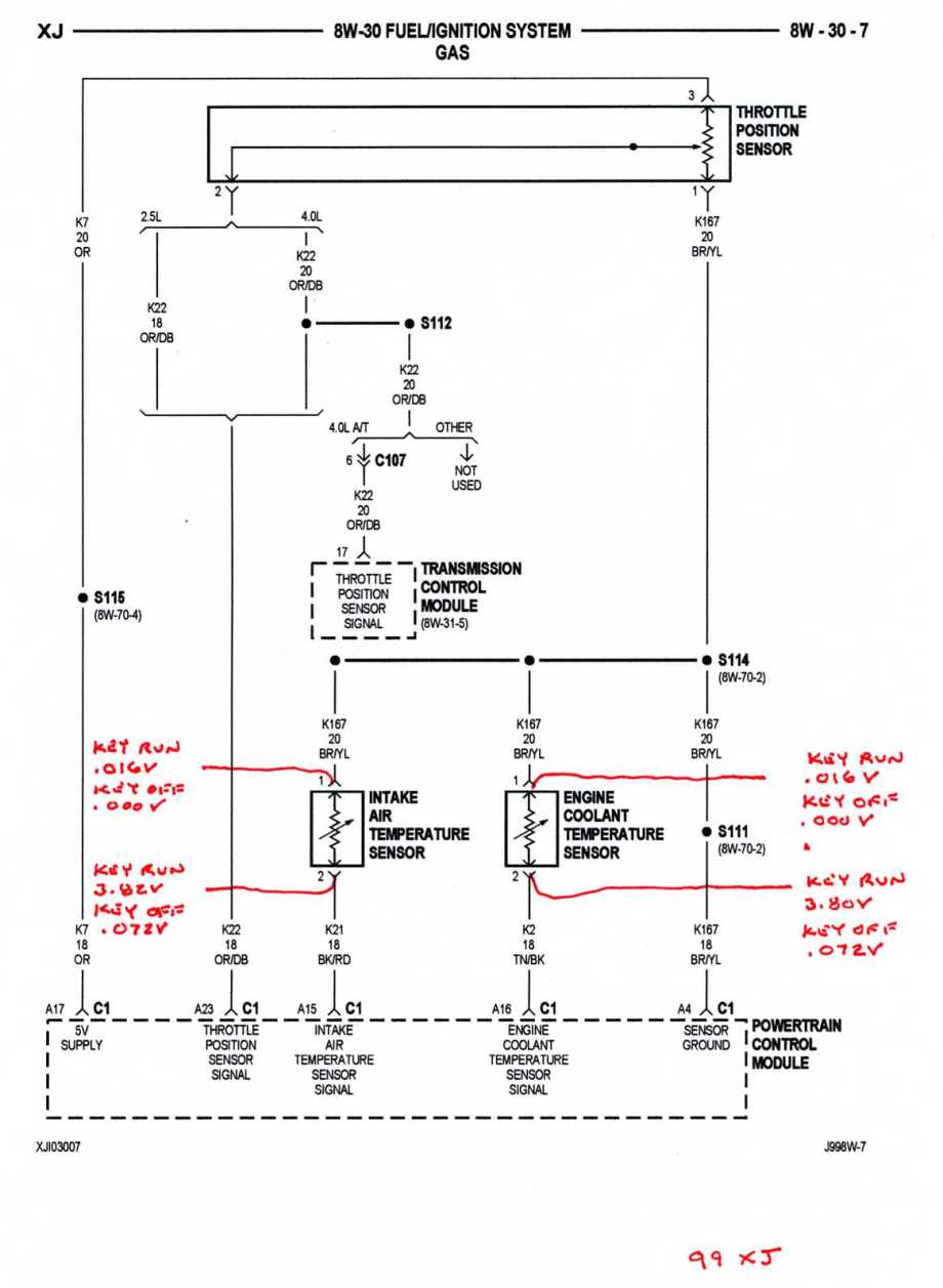
This is as close to a test as I can get. I did tests of the ECT and IAT sensors for the fun of it and recorded my findings.
The tests were conducted with the sensors connected and back probing each wire at each connector. The ignition switch positions are noted - Key Run (Engine not running).
The tests were conducted at 75*F outside air temp, engine off all night.
The low voltage readings at the Brown/Yellow tracer wires are the sensor ground network for all 5 volt sensors (splice S111). Chrysler calls it a live ground. The voltage reading will normally be between .015 and .020 volts. If you see an off scale voltage (hi/low) suspect a bad splice in the harness or a chafe to a higher voltage source. If you are checking the ECT sensor you can verify the readings you see by testing the IAT sensor.
I still can't figure out how these sensors work - magic I guess. But I think the PCM sensor signal wire voltage will vary based upon the temperature the sensor is feeling.
.
.
Not yet, working a lot hopefully this evening or tomorrow I will test the sensors Thanks I will follow up. I have tested the sensors now ,results below


Nice diagram ken, is that from the oem service manual? do you have a link to the dl if it's free?
CF Veteran
Quote:
Originally Posted by 97grand4.0
Nice diagram ken, is that from the oem service manual? do you have a link to the dl if it's free?
It is from my 1999 XJ FSM.
You can go to Pacific Coast Manuals and download a pdf copy of your Factory Service Manual. Only $7.95.
Here's the Grand Cherokee section -
http://www.pacificcoastmanuals.com/j...e_manuals.html
Quote:
You can go to Pacific Coast Manuals and download a pdf copy of your Factory Service Manual. Only $7.95.
Here's the Grand Cherokee section -
http://www.pacificcoastmanuals.com/j...e_manuals.html
Thanks , I have an xj and a zj. Nothing like the fsm.Originally Posted by CCKen
It is from my 1999 XJ FSM.You can go to Pacific Coast Manuals and download a pdf copy of your Factory Service Manual. Only $7.95.
Here's the Grand Cherokee section -
http://www.pacificcoastmanuals.com/j...e_manuals.html
CF Veteran
Quote:
Originally Posted by 97grand4.0
Thanks , I have an xj and a zj. Nothing like the fsm.
Exacto Facto.

Hi ken I finally tested those sensors I tried to send a picture of the results but I'm not sure if they went through was you able to see them?
Ken test results IAT Br-yl off .000 ECT Br/yl off .000
Keyon.016. Keyon .016
Bl/rd off .072. Tn/bl off .000
Key .0L. Key .016
Definitely some differences from what you were diagram showed what do you suggest
Keyon.016. Keyon .016
Bl/rd off .072. Tn/bl off .000
Key .0L. Key .016
Definitely some differences from what you were diagram showed what do you suggest
CF Veteran
Quote:
Keyon.016. Keyon .016
Bl/rd off .072. Tn/bl off .000
Key .0L. Key .016
Definitely some differences from what you were diagram showed what do you suggest
Originally Posted by Skinny
Ken test results IAT Br-yl off .000 ECT Br/yl off .000Keyon.016. Keyon .016
Bl/rd off .072. Tn/bl off .000
Key .0L. Key .016
Definitely some differences from what you were diagram showed what do you suggest
I don't understand the figures (I highlighted).
But the ground network (BR/YL) looks okay. If there is any variation coming from the PCM you should examine the wires from the ECT sensor to the PCM. That TN/BK wire from the ECT to the PCM is a straight shot, without splices or connectors en route so any chafing/breakage should be noticeable. If the wire looks okay the driver in the PCM may be shot.
Did it not make sense the way I listed them , I had them lined up in colums but they shifted on me IAT bk/rd key on OL. ECT Tn/bk Kenyon .016
CF Veteran
Quote:
Originally Posted by Skinny
Did it not make sense the way I listed them , I had them lined up in colums but they shifted on me IAT bk/rd key on OL. Tn/bk Kenyon .016
This is what has me stumped=Key .0L. Key .016
I'll get back tomorrow with a pinout of PCM connector C1. Using a digital Ohmmeter (set at 200 Ohms), check the resistance of the Tan/Black tracer wire from PCM C1 Pin cav A16 to the ECT sensor connector.