

Seasoned Member
Quote:
i guess then i would need to replace that part of the harness to get it back to normal..or make it a more permenant, secure work-around...
Originally Posted by dham99
If i were to run a wire from the battery to the orange/black wire that is not getting a charge (by light or gauge), then where in that wire would i splice it in? and to which battery terminal? and if i screw anything up, Im hoping Im able to purchace that connector so i can still plug it into the alternator...i guess then i would need to replace that part of the harness to get it back to normal..or make it a more permenant, secure work-around...
The only problem I have is my schematic does not show me where the wire with the charge indicator connects. It would seem to me that it goes thru the ignition switch but the schematic does not show it that way. Also the charge indicator is usually on the other wire like in the link that I posted above. Not sure if you have a light or gauge. Also not sure if you wire it differently if light or gauge. Also not sure if that wire is fused or not.
I have searched for wiring as in your vehicle but cannot find any. I would hate for you to wire it up and then blow the regulator.
If you want to give it a try, I would get a 14ga. wire and put a ring terminal on it and attach it to the starter relay where all the positive leads connect. On the other end attach an alligator clip.
The terminal on the alternator appears to be a female hole for the pins in the wire connector on the harness. Find a copper wire that fits snugly in the alternator hole. Cut 2 short leads and strip the ends and stick in the alterntor hole. Do not let the 2 wires make any electrical contact.
Connect the new wire alligator clip to the short lead that corresponds with the orange and black wire. Get some small alligator clips and wire a jumper with clips on each end. Connect one clip to the pin for the yellow wire and the other end to the other alternator wire lead.
They sell micro alligator clips that are insulated. Try to use them and do not let the clip on the harness pin touch the other pin.
Now you are wired up. Attach a voltmeter to the B+ alternator terminal so you can read voltage as someone starts the engine. If things do not look right during start up just pull the wires to stop the action.
Any way hope this works if you try it. You might stop by an auto electric shop and see if you can get any good info from them.
BTW, NAPA sells different wiring adapters. You might find an adapter there if needed.
The voltage reading should be 14-15 volts. Do not let it go over 16 volts.
Thanks for the good info ET! Ill have to try that when i get a chance..was just out messing around and its dark and the skeeters are killin me (out of OFF!)...
I regrounded the 4 wires and the NEG battery terminal to the block. All clean and tightened up.
I pulled the ground wire (think its ground) going to the Starter, and the wire going to the OPS (oil pressure sensor?) by the oil filter. those wires look good.
Started it all back up. As usual. The wierd thing Ive noticed is it goes straight to about 13+ on the gauge after about 5 or 10 seconds, for maybe about 2 seconds, then drops to the solid 9 or 10 amps on the gauge. then sometimes if i drive it around the block, its static at 9 or 10 without moving a hair (unless i draw more it goes down), and then strangly it'll get a charge and go up to about 13, then back down all for about a second. that is very rare. This to me sounds like something is loose and TRYING to run current, but it cant.
If those two are for sure supposed to have connection, I know F does (yellow wire). But if that other is not, (black and orange), then Ill try your method. Im just weary as Im tryign to picture what youre saying. Without knowing the other end of that black and orange, its risky. I guess thats my mission next, find the other end. But Im fairly certain it goes into that 6wire connector, big flat one in the pictures. From there, the wires are all tightly packed and I guess Ill have to start pulling them and inspecting...I just wish i knew for a fact if those two in the pigtail/4pin connector were SUPPOSED to be getting a charge.
Also, Ive noticed when I run the rig up an incline about 45 degrees or more, I can see the engine light on. But when I dip her back down closer to level, it goes off. its VERY consistant, as i did it many times. That too is odd...maybe there is a short somewhere...why would a light go on ONLY when the vehicle is inclinded, unless its pushing or pulling a wire somewhere that makes it touch or contact something... the hood light goes to a ground then the other one goes to the Main Starter Relay junction with everything else (and a 15amp fuse spliced in). that never blows, its always good.
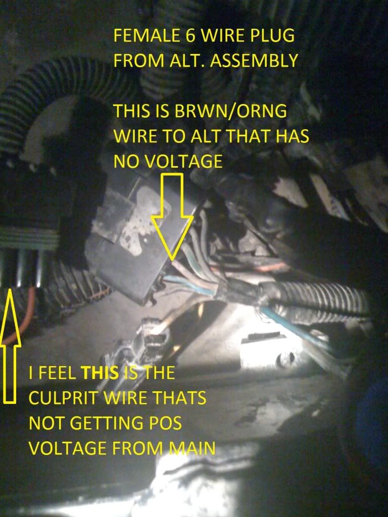
Alright guys, thanks to your help, I think I've narrowed it down to the culprit!!
PICS
1. Starter/Oil Pressure Sensor wire (just took off, cleaned, reconnected)
2. 4 pin connects to ALT
3. 6 pin male/female from ALT to MAIN Junction
4. 6 pin female from ALT
5. 6 pin male to MAIN (brown/orange), no voltage
6. 6 pin male to MAIn (any of the other 5 ports), full voltage
Now i have to splice from the Main to the Female Brown/Orange 6 pin somehow, to give the 6 pin female power to the ALT. Then i wont have to mess with the female end into the ALT at all...what do you think?
CF Veteran
http://http://jeepgarage.free.fr/OWN...agrams.pdfcant get the link to work
Quote:
not sure what that means...but the schematics you sent over (pdf) of the electronics layout is good. it shows that tan/grn goes to the instrument cluster. It clearly shows the red, then the yellow, but mine is an orange/brown..maybe it is grn/tan really..?Originally Posted by freegdr
9hibnj
that means running it to the power main isnt a good idea..and infact maybe that means it 'shouldnt' have power with the ign off like the other 5 pins...damn
CF Veteran
just clearing the link that did not work glad you got it
CF Veteran
you have checked to make sure the alt is grounded right by using the meter on the alt only from red post on alt to the casing of alt with blk from meter
Quote:
i do need to check that, i dont think i did a stand alone ground test for the Alt.Originally Posted by freegdr
you have checked to make sure the alt is grounded right by using the meter on the alt only from red post on alt to the casing of alt with blk from meter
you have good suggestions and know your stuff...but you always have run on sentances and sometimes I dont understand it until i read it like 10x lol...
So for a simple ground test on the Alt, i just take the POS multimeter post, touch it to the "BATT+" (positive) and the NEG (black) multimeter post to any spot on the Alternator housing? do i set it to 20v like when testing the battery and stuff? which is the specific ground test setting?
CF Veteran
sorry do not use meter on bat just alt redpf meter to red of alt blk to casing of alt 20v yes im trying all the stuff ive learned thru the years my dad was master tech thats like the god of ase certifications
CF Veteran
also my alternator is starting to act up so im trying to help you which helps me
yeah when I type "BATT+" thats what the Alternator says right next to the red power connection. So not "battery", but BATT as in, the alt gets its supply from that spot.
Okay Ill test it tomorrow after work, Its 130 here and i get up for work in 4.5 hours!
Thanks for ur help.
I just need to know what Im going to do as far as that wire thats not getting charge (when not running), or if it even should.
Okay Ill test it tomorrow after work, Its 130 here and i get up for work in 4.5 hours!
Thanks for ur help.
I just need to know what Im going to do as far as that wire thats not getting charge (when not running), or if it even should.