
Need help identifying connector in dash harness

CF Veteran
Joined: Aug 2010
Posts: 8,357
Likes: 103
From: Canton, MI
Year: 1999
Model: Cherokee
Engine: 4.0

Thread Starter
Junior Member
Joined: Nov 2012
Posts: 62
Likes: 0
From: LaPorte, IN
Year: 1998
Model: Cherokee
Engine: 4.0
are there any specific ground connections I should be looking at for the blower? Also, When I switch the blower speeds I think I hear a click from the relay.
Last edited by losixfor; Jan 18, 2013 at 10:46 AM.

Herp Derp Jerp

Joined: Nov 2011
Posts: 18,251
Likes: 17
From: Parham, ON
Year: 1999
Model: Cherokee
Engine: 4.0L OBD-II
From my 99's FSM:

That would be Fuse 25 behind the passenger kick panel to operate the relay, Fuse 6 in the PDC for the fan itself. No idea if this is the same on a 98
That would be Fuse 25 behind the passenger kick panel to operate the relay, Fuse 6 in the PDC for the fan itself. No idea if this is the same on a 98
CF Veteran
Joined: Aug 2010
Posts: 8,357
Likes: 103
From: Canton, MI
Year: 1999
Model: Cherokee
Engine: 4.0
There's not much difference between the '99 diagram and the '97 diagram (98 in between) so I think the '99 diagram should apply, except the blend door actuator.
losixfor,
As can be seen in Salad's diagram G108 is the ground points. G108 is a PITA to get at so you can use an Ohmeter to see if some of the circuits are complete.
First, detach the battery negative cable.
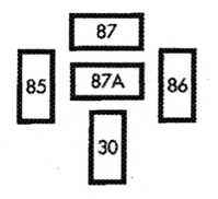
Remove the blower motor relay and (ref diagram) read from body harness relay base pin socket 85 to the dashboard stucture, you should read continuity. This checks the relay control coil ground circuit to G108.
Next, detach the connector from the blower motor resistor pack,
On the A/C Heat control panel select one of the two heat selections (ref. 7 or 8 in the diagram), rotate the blower speed control to the first (low) setting,
Using your Ohmeter, read from the resistor pack body harness connector, pin socket 7 (ref diagram), AWG 12, Black/Tan tracer wire, to the dashboard structure, you should read continuity. As you can see this tests the circuit from the blower motor resistor, through the A/C Heat control selectors, to G108.
Reconnect the battery negative cable.
Using a Voltmeter, read from body harness relay base pin socket 30 to the dashboard stucture, you should read battery voltage. This checks power from fuse 6 in the PDC to the relay.
Does this make sense?
Thread Starter
Junior Member
Joined: Nov 2012
Posts: 62
Likes: 0
From: LaPorte, IN
Year: 1998
Model: Cherokee
Engine: 4.0
So I ran home at lunch real quick. Pulled the blower motor. Tested the leads to the blower motor. Green gets 12v with key on (and heat on). and Black get continuity to ground. Is that how the resistor is checked, check the resistance on the black wire on different fan speeds? Should there be continuity to ground when the key is off? Also, I checked the motor at work with a 12v power supply. Seems to be working.
Last edited by losixfor; Jan 18, 2013 at 01:39 PM.
Thread Starter
Junior Member
Joined: Nov 2012
Posts: 62
Likes: 0
From: LaPorte, IN
Year: 1998
Model: Cherokee
Engine: 4.0
Salad,
There's not much difference between the '99 diagram and the '97 diagram (98 in between) so I think the '99 diagram should apply, except the blend door actuator.
losixfor,
As can be seen in Salad's diagram G108 is the ground points. G108 is a PITA to get at so you can use an Ohmeter to see if some of the circuits are complete.
First, detach the battery negative cable.
Remove the blower motor relay and (ref diagram) read from body harness relay base pin socket 85 to the dashboard stucture, you should read continuity. This checks the relay control coil ground circuit to G108.
Next, detach the connector from the blower motor resistor pack,
On the A/C Heat control panel select one of the two heat selections (ref. 7 or 8 in the diagram), rotate the blower speed control to the first (low) setting,
Using your Ohmeter, read from the resistor pack body harness connector, pin socket 7 (ref diagram), AWG 12, Black/Tan tracer wire, to the dashboard structure, you should read continuity. As you can see this tests the circuit from the blower motor resistor, through the A/C Heat control selectors, to G108.
Reconnect the battery negative cable.
Using a Voltmeter, read from body harness relay base pin socket 30 to the dashboard stucture, you should read battery voltage. This checks power from fuse 6 in the PDC to the relay.
Does this make sense?
Herp Derp Jerp
Joined: Nov 2011
Posts: 18,251
Likes: 17
From: Parham, ON
Year: 1999
Model: Cherokee
Engine: 4.0L OBD-II
So I ran home at lunch real quick. Pulled the blower motor. Tested the leads to the blower motor. Green gets 12v with key on (and heat on). and Black get continuity to ground. Is that how the resistor is checked, check the resistance on the black wire on different fan speeds? Should there be continuity to ground when the key is off? Also, I checked the motor at work with a 12v power supply. Seems to be working.
CF Veteran
Joined: Aug 2010
Posts: 8,357
Likes: 103
From: Canton, MI
Year: 1999
Model: Cherokee
Engine: 4.0
Here's an image of the Blower Motor Relay base pin cavities. Refer to the diagram for the associated circuits, and the instructions above for checking the relay ground circuit from pin cavity 85 to the dash structure.
Thread Starter
Junior Member
Joined: Nov 2012
Posts: 62
Likes: 0
From: LaPorte, IN
Year: 1998
Model: Cherokee
Engine: 4.0
Thanks for the help guys! I figured it out you are all wrong! Jkjk so apparently when I put the hvac box halves together after I replaced the heater core part of the shroud around the fan was misaligned. It was hitting the blower wheel and preventing it from rotating. Pulled blower worked fine put back in didn't, I was stumped for a while. Ended up having to pull the dash again (only partly assembled), and remove the hvac box, pull it apart and fix it. Got it done and back in. However now due to the stuck blower it seems I've fried my resistor. Blower only works on high now, but at least it works. Stupid mistake that caused me 2 hours. It's funny how fast you can do something a second time. Practice makes perfect. Moral of the story make sure the fan shroud interior of the hvac box is in the correct location before bolting it back together. It appears like it's a separate piece. Cheers time for beer

Thread
Thread Starter
Forum
Replies
Last Post
Brandonrcm
Accessories
10
Dec 2, 2015 07:48 PM
evguy
Stock XJ Cherokee Tech. All XJ Non-modified/stock questions go here
14
Sep 27, 2015 10:58 AM
Currently Active Users Viewing This Thread: 1 (0 members and 1 guests)