
FIRE!!! ahhh!!Ok, so i did the timing chain, fixed flex plate bolts, and went to fire


Thread Starter
Newbie
Joined: May 2010
Posts: 21
Likes: 0
From: Groveport, OH
Year: 2001
Model: Cherokee
Engine: 4.0 I6
Ok, so i did the timing chain, fixed flex plate bolts, and went to fire up the jeep, and it didn't start. It will turn over but wont start. THEN i notice fire spitting out of my intake. WHAT IN THE WORLD IS GOING ON?????
I'm at a lost here.
(this didnt happen till today?)
I'm at a lost here.
(this didnt happen till today?)

Seasoned Member
Joined: Aug 2010
Posts: 320
Likes: 1
From: Calgary, Alberta
Year: 1996
Model: Cherokee (XJ)
Engine: 4.0L
Ok, so i did the timing chain, fixed flex plate bolts, and went to fire up the jeep, and it didn't start. It will turn over but wont start. THEN i notice fire spitting out of my intake. WHAT IN THE WORLD IS GOING ON?????
I'm at a lost here.
(this didnt happen till today?)
I'm at a lost here.
(this didnt happen till today?)
CF Veteran
Joined: Sep 2010
Posts: 4,968
Likes: 0
From: Salt Lake City, UT
Year: 2000
Model: Cherokee
Engine: 4.0L
timing has to be off. either the chain is off. or if you rotated the gears independently of each other then the distributor is off, but you would have to turn the cam or crank 180* to cause this and have the chain lined up. but I would guess the t/chain is off.

CF Veteran
Joined: Nov 2010
Posts: 1,140
Likes: 1
From: cape cod ma.
Year: 1998
Model: Cherokee
Engine: 4.0 i6
no picture... but you can line the marks up and be at tdc but are you at the right stroke in the 4cycle series? piston could be at the top of exhaust stroke/start of intake stroke when it is firing...
CF Veteran
Joined: Nov 2010
Posts: 1,140
Likes: 1
From: cape cod ma.
Year: 1998
Model: Cherokee
Engine: 4.0 i6
also.. on some engines (small block chevy most common of which) the marks should be both in the same direction "up" when placing the distributor in the engine.. try pulling the distributor and spinning it 180 degrees. (not sure if that will work as these ignition systems are kinda funny)
Trending Topics
CF Veteran
Joined: Sep 2010
Posts: 4,968
Likes: 0
From: Salt Lake City, UT
Year: 2000
Model: Cherokee
Engine: 4.0L
how do you know its TDC? tdc is cyl 1 at top of stroke on compression (valves closed)
BDC can confuse a lot of people. it is when the piston is on the top of the stroke but exaust/intake valves are open. 360* off TDC
BDC can confuse a lot of people. it is when the piston is on the top of the stroke but exaust/intake valves are open. 360* off TDC
CF Veteran
Joined: Sep 2010
Posts: 4,968
Likes: 0
From: Salt Lake City, UT
Year: 2000
Model: Cherokee
Engine: 4.0L
do you have a compression tester? if you screw the hose on and leave the gauge off, cover the hole with your thumb sealing it. you can feel TDC when it starts to blow air past your finger while someone is turning the crank slowly. this is how i always verify TDC. its a lot easyer and cheaper then taking the head off.
before you take the head off i would look into a little more. i am confused as to how the timing is off if they are ligned up. as the cam would turn once for every 1 turn of the crank... so how could it be off... ? let me think for a min on this...
ok, looks like you have an after market cam gear installed. is there only 1 dot to align it with? i think mine had 2...
Last edited by Gorillaxj; Mar 28, 2011 at 12:22 AM.
Thread Starter
Newbie
Joined: May 2010
Posts: 21
Likes: 0
From: Groveport, OH
Year: 2001
Model: Cherokee
Engine: 4.0 I6
im not 100% sure unless i redo it. i know when i did the chain it was fine. but when i redid the distributor it's messing up.
it fired up yesterday. but today it's giving me problems. I put a new distributor in it and it's messing up now.
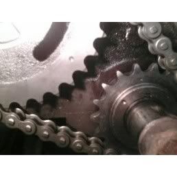
(http://s81.photobucket.com/albums/j2...ent=timing.jpg)
thats my timing marks when i did it. Am i correct if i messed up putting chain on it wouldnt start?
it fired up yesterday. but today it's giving me problems. I put a new distributor in it and it's messing up now.
(http://s81.photobucket.com/albums/j2...ent=timing.jpg)
thats my timing marks when i did it. Am i correct if i messed up putting chain on it wouldnt start?
Last edited by codyinc; Mar 28, 2011 at 12:22 AM.
CF Veteran
Joined: Sep 2010
Posts: 4,968
Likes: 0
From: Salt Lake City, UT
Year: 2000
Model: Cherokee
Engine: 4.0L
from the manual of setup...
-Installation of the timing chain with the timing marks on the crankshaft and camshaft sprockets properly aligned ensures correct valve timing. A worn or stretched timing chain will adversely affect valve timing. If the timing chain deflects more than 12.7 mm (1/2 inch) replace it. The correct timing chain has 48 pins. A chain with more than 48 pins will cause excessive slack.
-To verify correct installation of the timing chain, turn the crankshaft to position the camshaft sprocket timing mark as shown. Count the number of chain pins between the timing marks of both sprockets. There must be 15 pins
CF Veteran
Joined: Sep 2010
Posts: 4,968
Likes: 0
From: Salt Lake City, UT
Year: 2000
Model: Cherokee
Engine: 4.0L
Didn't mention the distributor had been out.
i bet your distributor is way off.... dont take your head off. don't remove the chain
before you remove your distributor check that the wires didn't get mixed up or reversed. wires being in the incorrect order can also cause this.
distributor replacement per manual.
Factory replacement distributors are equipped with a plastic alignment pin already installed. The pin is located in an access hole on the bottom of the distributor housing . It is used to temporarily lock the rotor to the cylinder number 1 position during installation. The pin must be removed after installing the distributor.
The camshaft position sensor is located in the distributor on all engines. Distributor removal is not necessary for sensor removal.
A fork with a slot is supplied on the bottom of the distributor housing where the housing base seats against the engine block . The centerline of the slot aligns with the distributor holddown bolt hole in the engine block. Because of the fork, the distributor cannot be rotated. Distributor rotation is not necessary as all ignition timing requirements are handled by the Powertrain Control Module (PCM) .
NOTE: Do not attempt to modify this fork to attain ignition timing. The position of the distributor determines fuel synchronization only. It does not determine ignition timing.
REMOVAL
Disconnect the negative battery cable at the battery.
Disconnect coil secondary cable at coil.
Remove distributor cap from distributor (2 screws). Do not remove cables from cap. Do not remove rotor.
Disconnect the distributor wiring harness from the main engine harness.
Remove the cylinder number 1 spark plug.
Hold a finger over the open spark plug hole. Rotate the engine at the vibration dampener bolt until compression (pressure) is felt.
Slowly continue to rotate the engine. Do this until the timing index mark on the vibration damper pulley aligns with the top dead center (TDC) mark (0 degree) on timing degree scale (Fig. 37) . Always rotate the engine in direction of normal rotation. Do not rotate the engine backward to align the timing marks.
On models equipped with A/C, remove the electrical cooling fan and shroud assembly from the radiator.
This will provide room to turn the engine crankshaft with a socket and ratchet using the vibration damper bolt.
Remove the distributor holddown bolt and clamp.
Remove the distributor from engine by slowly lifting straight up.
Note that the rotor will rotate slightly in a counterclockwise direction while lifting up the distributor. The oil pump gear will also rotate slightly in a counterclockwise direction while lifting up the distributor. This is due to the helical cut gears on the distributor and camshaft.
Note the removed position of the rotor during distributor removal. During installation, this will be referred to as the Pre-position
Observe the slot in the oil pump gear through the hole on the side of the engine. It should be slightly before (counterclockwise of) the 11 o'clock position .
Remove and discard the old distributor-to-engine block gasket.
INSTALLATION
If the engine crankshaft has been rotated after distributor removal, cylinder number 1 must be returned to its proper firing stroke. Refer to previous REMOVAL Step 5 and Step 6. These steps must be done before installing distributor.
Check the position of the slot on the oil pump gear. It should be just slightly before (counterclockwise of) the 11 o'clock position . If not, place a flat blade screwdriver into the oil pump gear and rotate it into the proper position.
Factory replacement distributors are equipped with a plastic alignment pin already installed. This pin is used to temporarily hold the rotor to the cylinder number 1 firing position during distributor installation. If this pin is in place, proceed to Step 8. If not, proceed to next step.
If the original distributor is to be reinstalled, such as during engine overhaul, the plastic pin will not be available. A 3/16 inch drift pin punch tool may be substituted for the plastic pin.
Remove the camshaft position sensor from the distributor housing. Lift straight up.
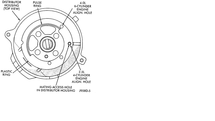
Four different alignment holes are provided on the plastic ring . Note that 2.5L and 4.0L engines have different alignment holes.
Rotate the distributor shaft and install the pin punch tool through the proper alignment hole in the plastic ring and into the mating access hole in the distributor housing. This will prevent the distributor shaft and rotor from rotating.
Clean the distributor mounting hole area of the engine block.
Install a new distributor-to-engine block gasket .
Install the rotor to the distributor shaft.
Pre-position the distributor into the engine while holding the centerline of the base slot in the 1 o'clock position (Fig. 41) . Continue to engage the distributor into the engine. The rotor and distributor will rotate clockwise during installation. This is due to the helical cut gears on the distributor and camshaft. When the distributor is fully seated to the engine block, the centerline of the base slot should be aligned to the clamp bolt mounting hole on the engine (Fig. 43) . The rotor should also be pointed at the 5 o'clock position .
It may be necessary to rotate the rotor and distributor shaft (very slightly) to engage the distributor shaft with the slot in the oil pump gear. The same may have to be done to engage the distributor gear with the camshaft gear.
The distributor is correctly installed when:
The rotor is pointed at the 5 o'clock position .
The plastic alignment pin (or pin punch tool) is still installed to distributor.
The number 1 cylinder piston is set at top dead center (TDC) (compression stroke).
The centerline of the slot at the base of the distributor is aligned to the centerline of the distributor holddown bolt hole on the engine. In this position, the holddown bolt should easily pass through the slot and into the engine.
If no adjustments are necessary Proceed to next step.
Install the distributor holddown clamp and bolt. Tighten the bolt to 23 Nm (17 ft. lbs.) torque.
Remove the pin punch tool from the distributor. Or, if the plastic alignment pin was used, remove it straight down from the bottom of the distributor. Discard plastic pin.
If removed, install the camshaft position sensor to the distributor. Align the wiring harness grommet to the notch in the distributor housing.
Install the rotor.
CAUTION: If the distributor cap is incorrectly positioned on distributor housing, the cap or rotor may be damaged when engine is started.
Install the distributor cap. Tighten distributor cap holddown screws to 3 Nm (26 in. lbs.) torque.
If removed, install the spark plug cables to the distributor cap. Engine Firing Order 1 5 3 6 2 4 .
Connect the distributor wiring harness to the main engine harness.
Connect battery cable to battery.
diagram
before you remove your distributor check that the wires didn't get mixed up or reversed. wires being in the incorrect order can also cause this.
distributor replacement per manual.
Factory replacement distributors are equipped with a plastic alignment pin already installed. The pin is located in an access hole on the bottom of the distributor housing . It is used to temporarily lock the rotor to the cylinder number 1 position during installation. The pin must be removed after installing the distributor.
The camshaft position sensor is located in the distributor on all engines. Distributor removal is not necessary for sensor removal.
A fork with a slot is supplied on the bottom of the distributor housing where the housing base seats against the engine block . The centerline of the slot aligns with the distributor holddown bolt hole in the engine block. Because of the fork, the distributor cannot be rotated. Distributor rotation is not necessary as all ignition timing requirements are handled by the Powertrain Control Module (PCM) .
NOTE: Do not attempt to modify this fork to attain ignition timing. The position of the distributor determines fuel synchronization only. It does not determine ignition timing.
REMOVAL
Disconnect the negative battery cable at the battery.
Disconnect coil secondary cable at coil.
Remove distributor cap from distributor (2 screws). Do not remove cables from cap. Do not remove rotor.
Disconnect the distributor wiring harness from the main engine harness.
Remove the cylinder number 1 spark plug.
Hold a finger over the open spark plug hole. Rotate the engine at the vibration dampener bolt until compression (pressure) is felt.
Slowly continue to rotate the engine. Do this until the timing index mark on the vibration damper pulley aligns with the top dead center (TDC) mark (0 degree) on timing degree scale (Fig. 37) . Always rotate the engine in direction of normal rotation. Do not rotate the engine backward to align the timing marks.
On models equipped with A/C, remove the electrical cooling fan and shroud assembly from the radiator.
This will provide room to turn the engine crankshaft with a socket and ratchet using the vibration damper bolt.
Remove the distributor holddown bolt and clamp.
Remove the distributor from engine by slowly lifting straight up.
Note that the rotor will rotate slightly in a counterclockwise direction while lifting up the distributor. The oil pump gear will also rotate slightly in a counterclockwise direction while lifting up the distributor. This is due to the helical cut gears on the distributor and camshaft.
Note the removed position of the rotor during distributor removal. During installation, this will be referred to as the Pre-position
Observe the slot in the oil pump gear through the hole on the side of the engine. It should be slightly before (counterclockwise of) the 11 o'clock position .
Remove and discard the old distributor-to-engine block gasket.
INSTALLATION
If the engine crankshaft has been rotated after distributor removal, cylinder number 1 must be returned to its proper firing stroke. Refer to previous REMOVAL Step 5 and Step 6. These steps must be done before installing distributor.
Check the position of the slot on the oil pump gear. It should be just slightly before (counterclockwise of) the 11 o'clock position . If not, place a flat blade screwdriver into the oil pump gear and rotate it into the proper position.
Factory replacement distributors are equipped with a plastic alignment pin already installed. This pin is used to temporarily hold the rotor to the cylinder number 1 firing position during distributor installation. If this pin is in place, proceed to Step 8. If not, proceed to next step.
If the original distributor is to be reinstalled, such as during engine overhaul, the plastic pin will not be available. A 3/16 inch drift pin punch tool may be substituted for the plastic pin.
Remove the camshaft position sensor from the distributor housing. Lift straight up.
Four different alignment holes are provided on the plastic ring . Note that 2.5L and 4.0L engines have different alignment holes.
Rotate the distributor shaft and install the pin punch tool through the proper alignment hole in the plastic ring and into the mating access hole in the distributor housing. This will prevent the distributor shaft and rotor from rotating.
Clean the distributor mounting hole area of the engine block.
Install a new distributor-to-engine block gasket .
Install the rotor to the distributor shaft.
Pre-position the distributor into the engine while holding the centerline of the base slot in the 1 o'clock position (Fig. 41) . Continue to engage the distributor into the engine. The rotor and distributor will rotate clockwise during installation. This is due to the helical cut gears on the distributor and camshaft. When the distributor is fully seated to the engine block, the centerline of the base slot should be aligned to the clamp bolt mounting hole on the engine (Fig. 43) . The rotor should also be pointed at the 5 o'clock position .
It may be necessary to rotate the rotor and distributor shaft (very slightly) to engage the distributor shaft with the slot in the oil pump gear. The same may have to be done to engage the distributor gear with the camshaft gear.
The distributor is correctly installed when:
The rotor is pointed at the 5 o'clock position .
The plastic alignment pin (or pin punch tool) is still installed to distributor.
The number 1 cylinder piston is set at top dead center (TDC) (compression stroke).
The centerline of the slot at the base of the distributor is aligned to the centerline of the distributor holddown bolt hole on the engine. In this position, the holddown bolt should easily pass through the slot and into the engine.
If no adjustments are necessary Proceed to next step.
Install the distributor holddown clamp and bolt. Tighten the bolt to 23 Nm (17 ft. lbs.) torque.
Remove the pin punch tool from the distributor. Or, if the plastic alignment pin was used, remove it straight down from the bottom of the distributor. Discard plastic pin.
If removed, install the camshaft position sensor to the distributor. Align the wiring harness grommet to the notch in the distributor housing.
Install the rotor.
CAUTION: If the distributor cap is incorrectly positioned on distributor housing, the cap or rotor may be damaged when engine is started.
Install the distributor cap. Tighten distributor cap holddown screws to 3 Nm (26 in. lbs.) torque.
If removed, install the spark plug cables to the distributor cap. Engine Firing Order 1 5 3 6 2 4 .
Connect the distributor wiring harness to the main engine harness.
Connect battery cable to battery.
diagram
Last edited by Gorillaxj; Mar 28, 2011 at 12:55 AM.
CF Veteran
Joined: Nov 2010
Posts: 1,140
Likes: 1
From: cape cod ma.
Year: 1998
Model: Cherokee
Engine: 4.0 i6
do you have a compression tester? if you screw the hose on and leave the gauge off, cover the hole with your thumb sealing it. you can feel TDC when it starts to blow air past your finger while someone is turning the crank slowly. this is how i always verify TDC. its a lot easyer and cheaper then taking the head off.
before you take the head off i would look into a little more. i am confused as to how the timing is off if they are ligned up. as the cam would turn once for every 1 turn of the crank... so how could it be off... ? let me think for a min on this...
ok, looks like you have an after market cam gear installed. is there only 1 dot to align it with? i think mine had 2...
before you take the head off i would look into a little more. i am confused as to how the timing is off if they are ligned up. as the cam would turn once for every 1 turn of the crank... so how could it be off... ? let me think for a min on this...
ok, looks like you have an after market cam gear installed. is there only 1 dot to align it with? i think mine had 2...
close but the cam spins at 1/2 the speed of the crank...thats why the spockets are two different sizes....i will bet you are 180 out common screw up trust me its a 5 min fix worth a shot...