

 Sep 10, 2015, 03:18 PM
Last edit by: IB Advertising
See related guides and technical advice from our community experts:
Browse all: Cooling System Guides
- Jeep Cherokee XJ 1984 to 1996 Why is Radiator Fan Not Working
Guide to diagnose trouble and recommended solutions
Browse all: Cooling System Guides

cooling fan function

Thread Starter
Newbie
Joined: Apr 2012
Posts: 2
Likes: 0
Model: Cherokee
i have looked all over and no one can properly answer my questions. i have a 2000 xj 4.0. i cant get the electric fan to work with the ac on. fuses and relays are ok. ac system is ok. fan is ok. if i unplug the pressure sensors or the coolant temp it will not turn on. cant find the wiring diagrams for 2000 any where, everything is 98 or older. if i had a proper wiring diagram i could trouble shoot without having to guess or trace wires. is there a diode on the 2000 for the fan? can the pcm really go bad? i would like to find the solution but im ready to wire a new relay in so that the ac clutch activates the fan. i am thinking that the blue/pink wire needs to be grounded by the pcm for the fan to work. if i ground it manually it works. so what gives? any takers? someone out there has to have had the same problem? oh and i also checked the grounding cluster on the driver side fender.
CF Veteran
Joined: Nov 2009
Posts: 8,172
Likes: 17
From: The Republic of TEXAS
Year: 1998
Model: Cherokee
Engine: 4.0L HO
On '00-'01 XJs, the efan is NOT a/c activated, only 218F coolant temp activated. Efan should default to "on" when connector at t-stat sending unit is unplugged. There have been posts that the dealer can re-program the ECU to turn efan on with a/c compressor like '99 down XJs.
Last edited by djb383; Apr 28, 2012 at 04:32 PM.


CF Veteran
Joined: Aug 2010
Posts: 8,357
Likes: 103
From: Canton, MI
Year: 1999
Model: Cherokee
Engine: 4.0
in addition to the coolant overtemp protection fan function, the 2000 and 2001 radiator fan is designed to work when the air conditioning is selected, to draw air over the condensor, except the high pressure switch is different from the earlier xj's. the '00/'01 high pressure switch is called a dual function switch, where there's a set of contacts that activates the fan and another set of contacts to activate the clutch. the low pressure cycling switch on the accumulator is wired in series with the fan contacts in the dual function switch. to test the fan circuit the low pressure switch connector would need to be jumpred and the high pressure switch contacts for the fan in the connector would need to be jumpered. ac needs to be selected on the hvac control panel and the engine started. the fan should run.
i'll send some diagrams and text from the '00 fsm that explains all this stuff.
cheers.
i'll send some diagrams and text from the '00 fsm that explains all this stuff.
cheers.
CF Veteran
Joined: Aug 2010
Posts: 8,357
Likes: 103
From: Canton, MI
Year: 1999
Model: Cherokee
Engine: 4.0
Here's some info on the '00 & '01 XJ Electric Radiator Fan - in AC Mode:
Operation of the Low Pressure Cycling Switch and Dual Function High Pressure Switch, from the '00 FSM:
LOW PRESSURE CYCLING CLUTCH SWITCH DESCRIPTION
The low pressure cycling clutch switch is located on the top of the accumulator. The switch is screwed onto an accumulator fitting that contains a Schrader type valve, which allows the switch to be serviced without discharging the refrigerant system. The accumulator fitting is equipped with an O-ring to seal the switch connection.
OPERATION
The low pressure cycling clutch switch is connected in series electrically with the high pressure cut-off switch, between ground and the Powertrain Control Module (PCM). The switch contacts open and close causing the PCM to turn the compressor clutch on
and off. This regulates the refrigerant system pressure and controls evaporator temperature. Controlling the evaporator temperature prevents condensate water on the evaporator fins from freezing and obstructing air conditioning system air flow.
The low pressure cycling clutch switch contacts are open when the suction pressure is approximately 141 kPa (20.5 psi) or lower. The switch contacts will close when the suction pressure rises to approximately 234 to 262 kPa (34 to 38 psi) or above. Lower ambient
temperatures, below approximately -1� C (30� F), will also cause the switch contacts to open. This is due to the pressure/temperature relationship of the refrigerant in the system. The low pressure cycling clutch switch is a factory calibrated unit. It cannot be adjusted or repaired
and, if faulty or damaged, it must be replaced.
DUAL FUNCTION HIGH PRESSURE SWITCH (4.0 L) DESCRIPTION
The Dual Function High Pressure Switch controls both A/C clutch engagement/disengagement, and electric cooling fan operations. The switch is located on the discharge line near the compressor. The switch is screwed onto a fitting that contains a Schrader-type valve, which allows the switch to be serviced without discharging the refrigerant system. The discharge
line fitting is equipped with an O-ring to seal the switch connection.
OPERATION
The dual function switch is connected in series electrically with the low pressure cycling clutch
switch between ground and the Powertrain Control Module (PCM). The switch contacts open and close causing the PCM to turn the compressor clutch on and off. This prevents compressor operation when the discharge line pressure approaches high levels, and also reduces electrical surging from compressor clutch engagement. The dual function switch controls the electric cooling fan operation by monitoring refrigerant line pressures. When the discharge line pressure rises above 1900 to 2200 kPa (280 to 320 psi) the fan will turn on. The cooling fan will turn off when the discharge line pressure drops to 1600 kPa (235 psi). The dual function switch controls the A/C clutch operation by disengaging the clutch when the discharge line pressure rises above 3100 to 3375 kPa (450 to 490 psi). The switch contacts will close and allow A/C clutch engagement when the discharge line pressure drops to 1860 to 2275 kPa (270 to 330 psi). The Dual Function High Pressure Switch is a factory- calibrated unit. The switch cannot be adjusted or repaired and, if faulty or damaged, it must be replaced.
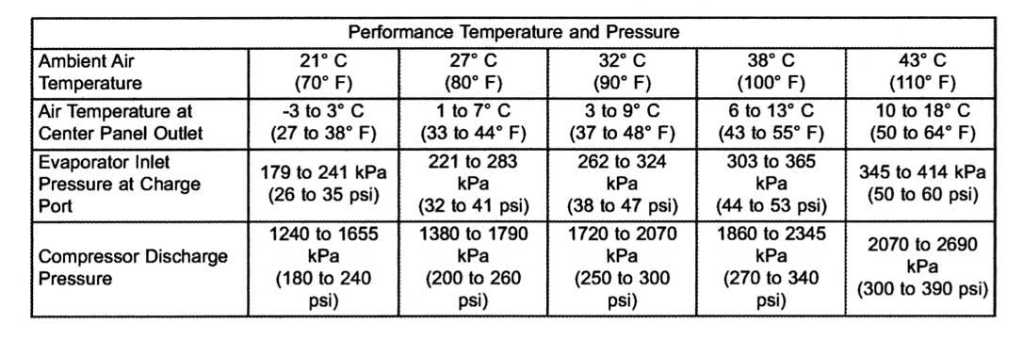
Here's a Temp/Pressure chhart that shows the outside air temp vs. compressor discharge high pressure. From the chart you can see that the fan will not turn on until the OAT is around 100*F to 110*F.
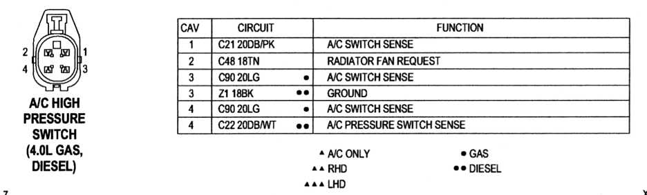
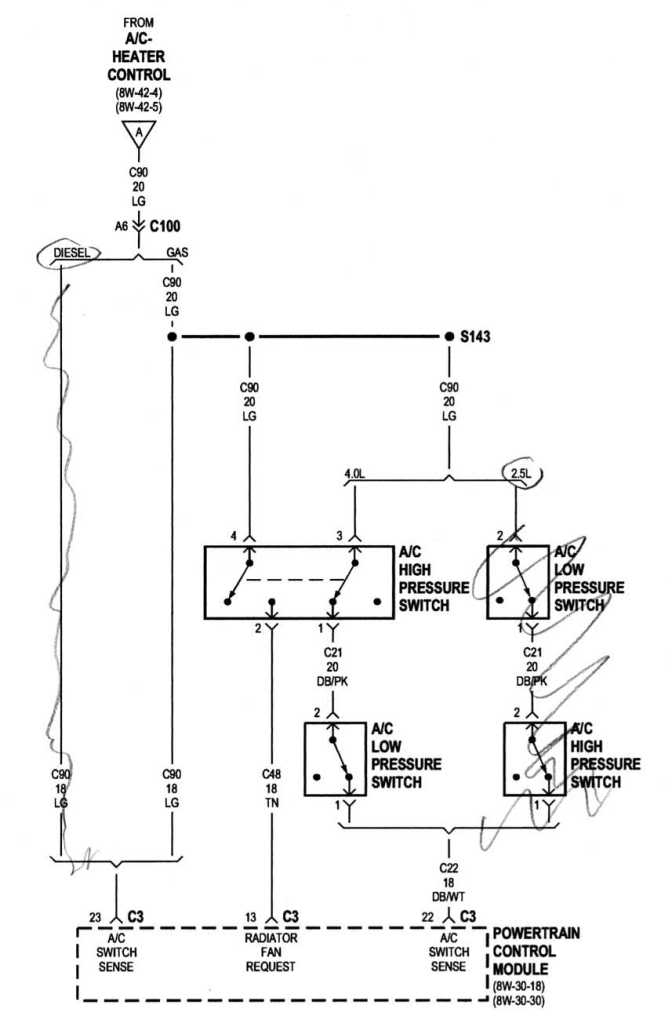
If your AC is working good and you just want to verify the fan will work at the high outside air temps, you can jumper the pin cavities in the Dual Function High Pressure Switch harness connector (leave the Low Pressure Cycling Switch connector installed) select AC on the HVAC control panel, then start the engine. The fan should run. If it doesn't, jumper the two pin cavities in the Low Pressure Cycling Switch as well and try it again. Refer to the following A/C High Pressure Switch connector pin out diagram below. Jumper pin cavities 4 to 2, and cavities 1 to 3 (see also wiring diagram below). If you are using paper clips to jumper the pin cavities, do not force the clip wires into the cavities. If neccessary, file the ends of the clip wires down so they snugly fit the pin cavities.
Operation of the Low Pressure Cycling Switch and Dual Function High Pressure Switch, from the '00 FSM:
LOW PRESSURE CYCLING CLUTCH SWITCH DESCRIPTION
The low pressure cycling clutch switch is located on the top of the accumulator. The switch is screwed onto an accumulator fitting that contains a Schrader type valve, which allows the switch to be serviced without discharging the refrigerant system. The accumulator fitting is equipped with an O-ring to seal the switch connection.
OPERATION
The low pressure cycling clutch switch is connected in series electrically with the high pressure cut-off switch, between ground and the Powertrain Control Module (PCM). The switch contacts open and close causing the PCM to turn the compressor clutch on
and off. This regulates the refrigerant system pressure and controls evaporator temperature. Controlling the evaporator temperature prevents condensate water on the evaporator fins from freezing and obstructing air conditioning system air flow.
The low pressure cycling clutch switch contacts are open when the suction pressure is approximately 141 kPa (20.5 psi) or lower. The switch contacts will close when the suction pressure rises to approximately 234 to 262 kPa (34 to 38 psi) or above. Lower ambient
temperatures, below approximately -1� C (30� F), will also cause the switch contacts to open. This is due to the pressure/temperature relationship of the refrigerant in the system. The low pressure cycling clutch switch is a factory calibrated unit. It cannot be adjusted or repaired
and, if faulty or damaged, it must be replaced.
DUAL FUNCTION HIGH PRESSURE SWITCH (4.0 L) DESCRIPTION
The Dual Function High Pressure Switch controls both A/C clutch engagement/disengagement, and electric cooling fan operations. The switch is located on the discharge line near the compressor. The switch is screwed onto a fitting that contains a Schrader-type valve, which allows the switch to be serviced without discharging the refrigerant system. The discharge
line fitting is equipped with an O-ring to seal the switch connection.
OPERATION
The dual function switch is connected in series electrically with the low pressure cycling clutch
switch between ground and the Powertrain Control Module (PCM). The switch contacts open and close causing the PCM to turn the compressor clutch on and off. This prevents compressor operation when the discharge line pressure approaches high levels, and also reduces electrical surging from compressor clutch engagement. The dual function switch controls the electric cooling fan operation by monitoring refrigerant line pressures. When the discharge line pressure rises above 1900 to 2200 kPa (280 to 320 psi) the fan will turn on. The cooling fan will turn off when the discharge line pressure drops to 1600 kPa (235 psi). The dual function switch controls the A/C clutch operation by disengaging the clutch when the discharge line pressure rises above 3100 to 3375 kPa (450 to 490 psi). The switch contacts will close and allow A/C clutch engagement when the discharge line pressure drops to 1860 to 2275 kPa (270 to 330 psi). The Dual Function High Pressure Switch is a factory- calibrated unit. The switch cannot be adjusted or repaired and, if faulty or damaged, it must be replaced.
Here's a Temp/Pressure chhart that shows the outside air temp vs. compressor discharge high pressure. From the chart you can see that the fan will not turn on until the OAT is around 100*F to 110*F.
If your AC is working good and you just want to verify the fan will work at the high outside air temps, you can jumper the pin cavities in the Dual Function High Pressure Switch harness connector (leave the Low Pressure Cycling Switch connector installed) select AC on the HVAC control panel, then start the engine. The fan should run. If it doesn't, jumper the two pin cavities in the Low Pressure Cycling Switch as well and try it again. Refer to the following A/C High Pressure Switch connector pin out diagram below. Jumper pin cavities 4 to 2, and cavities 1 to 3 (see also wiring diagram below). If you are using paper clips to jumper the pin cavities, do not force the clip wires into the cavities. If neccessary, file the ends of the clip wires down so they snugly fit the pin cavities.
Thread Starter
Newbie
Joined: Apr 2012
Posts: 2
Likes: 0
Model: Cherokee
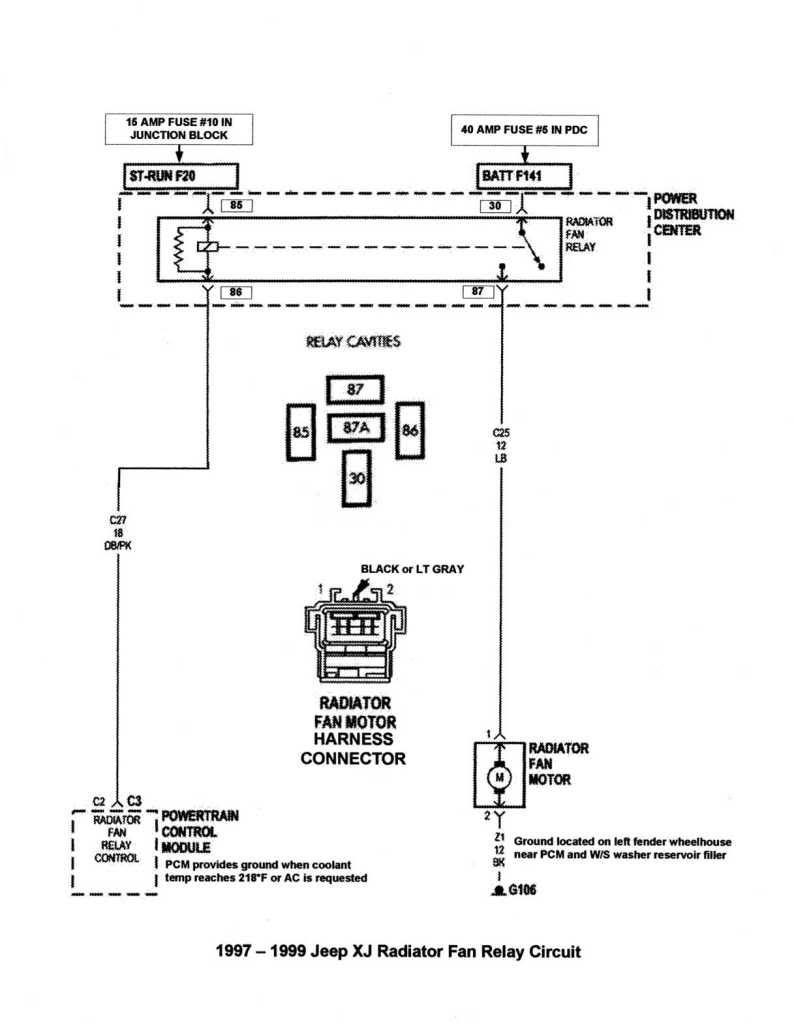
CCKen that is a great help! Thank you for taking the time to share that info. The right information makes all the difference. I've only had this xj for about a month. Its super clean and in amazing condition. Before I make any mods to it I want to make sure everything is right. I will post a my solution once I get it figured out. Thanks again! Do you have a diagram of the fan relay circuit? that would be awesome too.
Last edited by zrvxj; Apr 29, 2012 at 10:02 AM. Reason: add question
Trending Topics
CF Veteran
Joined: Aug 2010
Posts: 8,357
Likes: 103
From: Canton, MI
Year: 1999
Model: Cherokee
Engine: 4.0
If you are interested in finding out if your Radiator Fan will operate when your engine coolant temp gets too high you can perform the following test. I've done it on my '99 and it works well.
Testing Radiator Cooling Fan, Coolant Over-Temp Protection System � 1997-2001 XJ
Radiator cooling fan over-temperature protection operation overview:
When the Engine Coolant Temperature (ECT) Sensor signals the Powertrain Control Module (PCM) that the coolant temperature has reached approximately 218�F (�97-�99) or 223� F (�00-�01) the PCM will provide a ground path for the fan relay control coil *. Battery voltage is then applied to the fan through the relay. When coolant temperature drops below approximately 209�F (�97-�99) or 217� F (�00��01), the PCM opens the ground path to the relay control coil, preventing the cooling fan from being energized.
* The PCM must detect that the engine is running and that the Alternator is on line before it will provide a ground path to the fan relay control coil.
Test:
You�ll need a 470 Ohm resistor (from Radio Shack or other electronics outlet) to perform the test. The resistor takes the place of the ECT Sensor and simulates an approximate 235�F signal to the PCM.
Procedures:
1. Start the Jeep and allow the engine coolant to come up to normal operating temperature (210�F);
2. Shut down the engine and detach the harness connector from the Engine Coolant Temperature (ECT) Sensor;
3. Jumper the two pin cavities in the harness connector with the 470 Ohm resistor;
4. Turn the ignition switch to RUN (engine off) and observe the engine coolant temperature indicator, it should read approximately 235�F. The fan should not be operating;
5. Start the engine. The fan should now be operating;
6. Shut down engine. The fan should not be operating. Remove resistor, and reattach the ECT Sensor connector;
7. Turn ignition switch to RUN, the engine coolant temperature indicator should read at or below normal operating temperature. There should be no CHECK ENGINE or CHECK GAUGES light on the instrument panel;
8. End of test.
Here's a pic of the resistor in the ECT Connector.

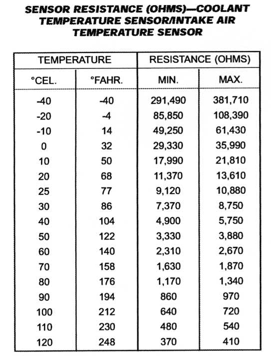
Here's a pic of the ECT/IAT sensor(s) temp vs. resistance. You'll see that a 470 Ohm rsistance will induce a temp of between 230*F and 248*F.
I've seen mention on the various XJ forums that if you disconnect the ECT the fan will run. I've never tried this so I have no idea if it will work. In theory it won't.
Testing Radiator Cooling Fan, Coolant Over-Temp Protection System � 1997-2001 XJ
Radiator cooling fan over-temperature protection operation overview:
When the Engine Coolant Temperature (ECT) Sensor signals the Powertrain Control Module (PCM) that the coolant temperature has reached approximately 218�F (�97-�99) or 223� F (�00-�01) the PCM will provide a ground path for the fan relay control coil *. Battery voltage is then applied to the fan through the relay. When coolant temperature drops below approximately 209�F (�97-�99) or 217� F (�00��01), the PCM opens the ground path to the relay control coil, preventing the cooling fan from being energized.
* The PCM must detect that the engine is running and that the Alternator is on line before it will provide a ground path to the fan relay control coil.
Test:
You�ll need a 470 Ohm resistor (from Radio Shack or other electronics outlet) to perform the test. The resistor takes the place of the ECT Sensor and simulates an approximate 235�F signal to the PCM.
Procedures:
1. Start the Jeep and allow the engine coolant to come up to normal operating temperature (210�F);
2. Shut down the engine and detach the harness connector from the Engine Coolant Temperature (ECT) Sensor;
3. Jumper the two pin cavities in the harness connector with the 470 Ohm resistor;
4. Turn the ignition switch to RUN (engine off) and observe the engine coolant temperature indicator, it should read approximately 235�F. The fan should not be operating;
5. Start the engine. The fan should now be operating;
6. Shut down engine. The fan should not be operating. Remove resistor, and reattach the ECT Sensor connector;
7. Turn ignition switch to RUN, the engine coolant temperature indicator should read at or below normal operating temperature. There should be no CHECK ENGINE or CHECK GAUGES light on the instrument panel;
8. End of test.
Here's a pic of the resistor in the ECT Connector.
Here's a pic of the ECT/IAT sensor(s) temp vs. resistance. You'll see that a 470 Ohm rsistance will induce a temp of between 230*F and 248*F.
I've seen mention on the various XJ forums that if you disconnect the ECT the fan will run. I've never tried this so I have no idea if it will work. In theory it won't.

Seasoned Member
Joined: Jul 2011
Posts: 324
Likes: 1
From: Richmond, Va
Year: 1992
Model: Cherokee
Engine: 4.0 liter I6
Yea after rebuilding my engine. New radiator, clutch fan, water pump, t-stat, new head and the works. I thought my e-fan was not coming on when it should. After checked with a infrared thermometer I found out that the gauge on the dash is not reading correctly and that I am actually running at 205* engine temp. No where near where it needs to be to kick the fan on. Comes on with the a/c and comes on when the temp sensor is unplugged. I just havent made it by radio shack to grab a resistor to make sure it is actually seeing the correct temp. I am with you though, just want to make sure everything is working as it should especially after I just got done doing a complete rebuild of the engine due to the previous owner running it hot because of the clogged radiator and cracked the head and milkshaked the engine. Let us know how it goes.
And yes the cooling fan should come on when the ECT sensor is unplugged. The PCM sees an open signal and does not know what the engine temp is so it defaults to turning the cooling fan on. Kinda a failsafe
And yes the cooling fan should come on when the ECT sensor is unplugged. The PCM sees an open signal and does not know what the engine temp is so it defaults to turning the cooling fan on. Kinda a failsafe

Newbie
Joined: Mar 2018
Posts: 16
Likes: 0
Model: Cherokee(SJ)
On '00-'01 XJs, the efan is NOT a/c activated, only 218F coolant temp activated. Efan should default to "on" when connector at t-stat sending unit is unplugged. There have been posts that the dealer can re-program the ECU to turn efan on with a/c compressor like '99 down XJs.
Here's some info on the '00 & '01 XJ Electric Radiator Fan - in AC Mode:
Operation of the Low Pressure Cycling Switch and Dual Function High Pressure Switch, from the '00 FSM:
LOW PRESSURE CYCLING CLUTCH SWITCH DESCRIPTION
The low pressure cycling clutch switch is located on the top of the accumulator. The switch is screwed onto an accumulator fitting that contains a Schrader type valve, which allows the switch to be serviced without discharging the refrigerant system. The accumulator fitting is equipped with an O-ring to seal the switch connection.
OPERATION
The low pressure cycling clutch switch is connected in series electrically with the high pressure cut-off switch, between ground and the Powertrain Control Module (PCM). The switch contacts open and close causing the PCM to turn the compressor clutch on
and off. This regulates the refrigerant system pressure and controls evaporator temperature. Controlling the evaporator temperature prevents condensate water on the evaporator fins from freezing and obstructing air conditioning system air flow.
The low pressure cycling clutch switch contacts are open when the suction pressure is approximately 141 kPa (20.5 psi) or lower. The switch contacts will close when the suction pressure rises to approximately 234 to 262 kPa (34 to 38 psi) or above. Lower ambient
temperatures, below approximately -1� C (30� F), will also cause the switch contacts to open. This is due to the pressure/temperature relationship of the refrigerant in the system. The low pressure cycling clutch switch is a factory calibrated unit. It cannot be adjusted or repaired
and, if faulty or damaged, it must be replaced.
DUAL FUNCTION HIGH PRESSURE SWITCH (4.0 L) DESCRIPTION
The Dual Function High Pressure Switch controls both A/C clutch engagement/disengagement, and electric cooling fan operations. The switch is located on the discharge line near the compressor. The switch is screwed onto a fitting that contains a Schrader-type valve, which allows the switch to be serviced without discharging the refrigerant system. The discharge
line fitting is equipped with an O-ring to seal the switch connection.
OPERATION
The dual function switch is connected in series electrically with the low pressure cycling clutch
switch between ground and the Powertrain Control Module (PCM). The switch contacts open and close causing the PCM to turn the compressor clutch on and off. This prevents compressor operation when the discharge line pressure approaches high levels, and also reduces electrical surging from compressor clutch engagement. The dual function switch controls the electric cooling fan operation by monitoring refrigerant line pressures. When the discharge line pressure rises above 1900 to 2200 kPa (280 to 320 psi) the fan will turn on. The cooling fan will turn off when the discharge line pressure drops to 1600 kPa (235 psi). The dual function switch controls the A/C clutch operation by disengaging the clutch when the discharge line pressure rises above 3100 to 3375 kPa (450 to 490 psi). The switch contacts will close and allow A/C clutch engagement when the discharge line pressure drops to 1860 to 2275 kPa (270 to 330 psi). The Dual Function High Pressure Switch is a factory- calibrated unit. The switch cannot be adjusted or repaired and, if faulty or damaged, it must be replaced.
Here's a Temp/Pressure chhart that shows the outside air temp vs. compressor discharge high pressure. From the chart you can see that the fan will not turn on until the OAT is around 100*F to 110*F.
Attachment 373912
If your AC is working good and you just want to verify the fan will work at the high outside air temps, you can jumper the pin cavities in the Dual Function High Pressure Switch harness connector (leave the Low Pressure Cycling Switch connector installed) select AC on the HVAC control panel, then start the engine. The fan should run. If it doesn't, jumper the two pin cavities in the Low Pressure Cycling Switch as well and try it again. Refer to the following A/C High Pressure Switch connector pin out diagram below. Jumper pin cavities 4 to 2, and cavities 1 to 3 (see also wiring diagram below). If you are using paper clips to jumper the pin cavities, do not force the clip wires into the cavities. If neccessary, file the ends of the clip wires down so they snugly fit the pin cavities.
Attachment 373913
Attachment 373914

Newbie
Joined: Jul 2024
Posts: 2
Likes: 0
You can test the pcm output that is supposed the activate the fan relay. At 223 *F it should send vdc to the primary side of the relay and shut off at 217 (specs feom a 2001 manual fyi)
I have had a good experience with FlagShipOne for an ECM for my Dodge. They have good prices, no core send in and a good warranty
I have had a good experience with FlagShipOne for an ECM for my Dodge. They have good prices, no core send in and a good warranty
i have looked all over and no one can properly answer my questions. i have a 2000 xj 4.0. i cant get the electric fan to work with the ac on. fuses and relays are ok. ac system is ok. fan is ok. if i unplug the pressure sensors or the coolant temp it will not turn on. cant find the wiring diagrams for 2000 any where, everything is 98 or older. if i had a proper wiring diagram i could trouble shoot without having to guess or trace wires. is there a diode on the 2000 for the fan? can the pcm really go bad? i would like to find the solution but im ready to wire a new relay in so that the ac clutch activates the fan. i am thinking that the blue/pink wire needs to be grounded by the pcm for the fan to work. if i ground it manually it works. so what gives? any takers? someone out there has to have had the same problem? oh and i also checked the grounding cluster on the driver side fender.

Thread
Thread Starter
Forum
Replies
Last Post
jmsummers2012
Stock XJ Cherokee Tech. All XJ Non-modified/stock questions go here
56
Jun 12, 2025 02:04 AM
scatgo
Stock XJ Cherokee Tech. All XJ Non-modified/stock questions go here
14
Mar 22, 2021 09:56 AM
LittleRed94
Stock XJ Cherokee Tech. All XJ Non-modified/stock questions go here
5
Oct 6, 2015 08:09 PM
Sandyman
Stock XJ Cherokee Tech. All XJ Non-modified/stock questions go here
10
Sep 29, 2015 06:33 PM
Currently Active Users Viewing This Thread: 1 (0 members and 1 guests)