
99 Cherokee Electrical Issues....


Thread Starter
Junior Member
Joined: Dec 2012
Posts: 48
Likes: 0
From: Catskills
Year: 1999
Model: Cherokee
Engine: 4.0
All the connectors looked good and clean
CF Veteran

Joined: Sep 2009
Posts: 8,567
Likes: 20
From: ☼ Blackhole Sun
Year: My Jeep is a GMC
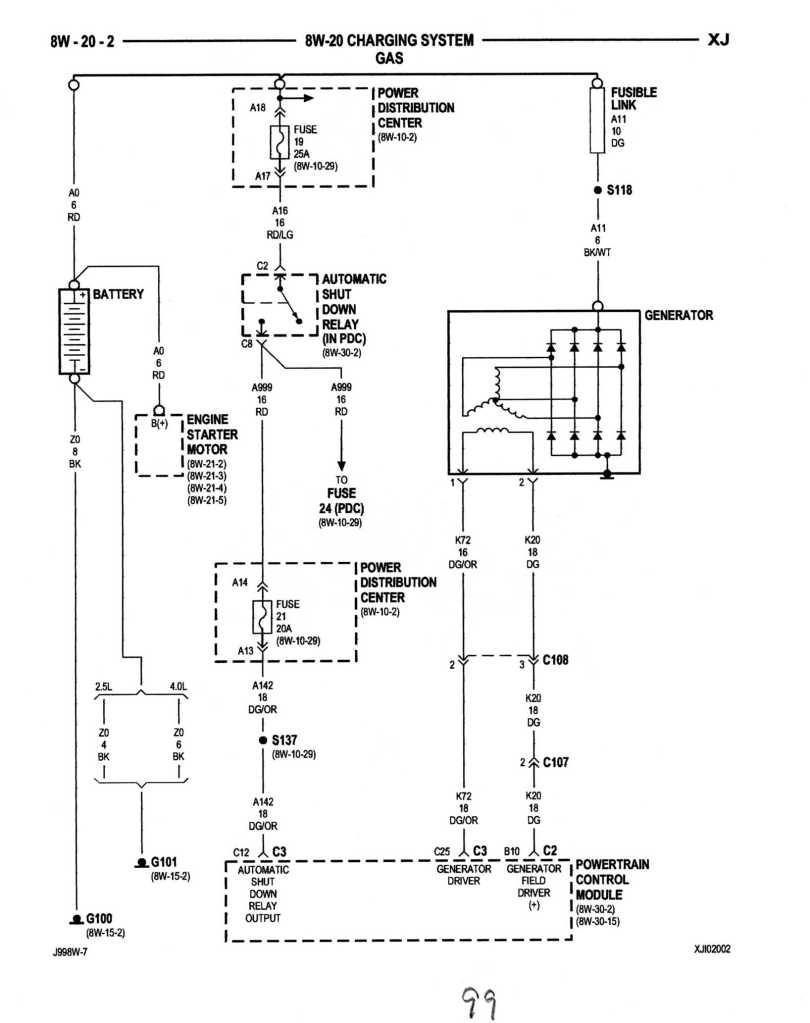
Disconnect the battery first, then refer back on P 2 to the pin-outs Salad posted for the ECU. Use a DMM on test continuity end to end of the wiring for 1. generator driver, 2. generator field driver: B10, C25, etc. With the probes in both connectors if you have continuity flex the wiring harness, see if you can cause to circuit to open due to a broken or damaged wire. If those first two circuits test good, then it's on to the grounds, this may take a while.
CF Veteran
Joined: Aug 2010
Posts: 8,357
Likes: 103
From: Canton, MI
Year: 1999
Model: Cherokee
Engine: 4.0
the o2 sensor was torn from offroading i believe and the battery temp sensor wires seem to be pressed on by the battery base plate. I'm going to get a new battery temp sensor and raise the battery up off the wires as well as replace the o2 sensor. I checked the grounds with a multimeter and they all seemed fine.
If it was a ground issue I would assume I would have the voltage issue as soon as the Jeep starts up but if it's a sensor issue it would be once the engine warms up and begins to read the sensors. Correct me if i'm wrong though.
If it was a ground issue I would assume I would have the voltage issue as soon as the Jeep starts up but if it's a sensor issue it would be once the engine warms up and begins to read the sensors. Correct me if i'm wrong though.
Your right in your assumption about the O2S. Once the engine coolant gets up to around 125*F the PCM goes into closed loop and brings the O2S's on line to be monitored. An upstream O2S with torn off wires should have triggered a CEL. Shorted O2S wires have been known to cook a PCM so be careful. That O2S would not cause an overvoltage situation.
Last edited by CCKen; Jan 4, 2013 at 07:45 PM.
CF Veteran
Joined: Aug 2010
Posts: 8,357
Likes: 103
From: Canton, MI
Year: 1999
Model: Cherokee
Engine: 4.0
From the 99 FSM:
CHARGING SYSTEM
DESCRIPTION
The charging system consists of:
OPERATION
The charging system is turned on and off with the ignition switch. The system is on when the engine is running and the ASD relay is energized. When the ASD relay is on, voltage is supplied to the ASD relay sense circuit at the PCM. This voltage is connected through the PCM and supplied to one of the generator field terminals (Gen. Source +) at the back of the generator.
The amount of DC current produced by the generator is controlled by the EVR (field control) circuitry contained within the PCM. This circuitry is connected in series with the second rotor field terminal and ground.
A battery temperature sensor, located in the battery tray housing, is used to sense battery temperature. This temperature data, along with data from monitored line voltage, is used by the PCM to vary the battery charging rate. This is done by cycling the ground path to control the strength of the rotor magnetic field. The PCM then compensates and regulates generator current output accordingly. All vehicles are equipped with On-Board Diagnostics (OBD). All OBD-sensed systems, including EVR (field control) circuitry, are monitored by the PCM.
Each monitored circuit is assigned a Diagnostic Trouble Code (DTC). The PCM will store a DTC in electronic memory for certain failures it detects. Refer to On-Board Diagnostics in Group 25, Emission Control System for more DTC information.
The Check Gauges Lamp (if equipped) monitors:
charging system voltage, engine coolant temperature and engine oil pressure. If an extreme condition is indicated, the lamp will be illuminated. This is done as reminder to check the three gauges. The signal to activate the lamp is sent via the CCD bus circuits. The lamp is located on the instrument panel.
BATTERY TEMPERATURE SENSOR
DESCRIPTION
The battery temperature sensor is attached to the battery tray located under the battery.
OPERATION
The battery temperature sensor is used to determine the battery temperature and control battery
charging rate. This temperature data, along with data from monitored line voltage, is used by the PCM to vary the battery charging rate. System voltage will be higher at colder temperatures and is gradually reduced at warmer temperatures.
ELECTRONIC VOLTAGE REGULATOR
DESCRIPTION
The Electronic Voltage Regulator (EVR) is not a separate component. It is actually a voltage regulating circuit located within the Powertrain Control Module (PCM). The EVR is not serviced separately. If replacement is necessary, the PCM must be replaced.
OPERATION
The amount of DC current produced by the generator is controlled by EVR circuitry contained within the PCM. This circuitry is connected in series with the generators second rotor field terminal and its ground. Voltage is regulated by cycling the ground path to control the strength of the rotor magnetic field. The EVR circuitry monitors system line voltage and battery
temperature (refer to Battery Temperature Sensor for more information). It then compensates and regulates generator current output accordingly. Also refer to Charging System Operation for additional information.
CHARGING SYSTEM
DESCRIPTION
The charging system consists of:
- Generator
- Electronic Voltage Regulator (EVR) circuitry within the Powertrain Control Module (PCM)
- Ignition switch
- Battery
- Battery temperature sensor
- Generator Lamp
- Check Gauges Lamp
- Voltmeter
- Wiring harness and connections
OPERATION
The charging system is turned on and off with the ignition switch. The system is on when the engine is running and the ASD relay is energized. When the ASD relay is on, voltage is supplied to the ASD relay sense circuit at the PCM. This voltage is connected through the PCM and supplied to one of the generator field terminals (Gen. Source +) at the back of the generator.
The amount of DC current produced by the generator is controlled by the EVR (field control) circuitry contained within the PCM. This circuitry is connected in series with the second rotor field terminal and ground.
A battery temperature sensor, located in the battery tray housing, is used to sense battery temperature. This temperature data, along with data from monitored line voltage, is used by the PCM to vary the battery charging rate. This is done by cycling the ground path to control the strength of the rotor magnetic field. The PCM then compensates and regulates generator current output accordingly. All vehicles are equipped with On-Board Diagnostics (OBD). All OBD-sensed systems, including EVR (field control) circuitry, are monitored by the PCM.
Each monitored circuit is assigned a Diagnostic Trouble Code (DTC). The PCM will store a DTC in electronic memory for certain failures it detects. Refer to On-Board Diagnostics in Group 25, Emission Control System for more DTC information.
The Check Gauges Lamp (if equipped) monitors:
charging system voltage, engine coolant temperature and engine oil pressure. If an extreme condition is indicated, the lamp will be illuminated. This is done as reminder to check the three gauges. The signal to activate the lamp is sent via the CCD bus circuits. The lamp is located on the instrument panel.
BATTERY TEMPERATURE SENSOR
DESCRIPTION
The battery temperature sensor is attached to the battery tray located under the battery.
OPERATION
The battery temperature sensor is used to determine the battery temperature and control battery
charging rate. This temperature data, along with data from monitored line voltage, is used by the PCM to vary the battery charging rate. System voltage will be higher at colder temperatures and is gradually reduced at warmer temperatures.
ELECTRONIC VOLTAGE REGULATOR
DESCRIPTION
The Electronic Voltage Regulator (EVR) is not a separate component. It is actually a voltage regulating circuit located within the Powertrain Control Module (PCM). The EVR is not serviced separately. If replacement is necessary, the PCM must be replaced.
OPERATION
The amount of DC current produced by the generator is controlled by EVR circuitry contained within the PCM. This circuitry is connected in series with the generators second rotor field terminal and its ground. Voltage is regulated by cycling the ground path to control the strength of the rotor magnetic field. The EVR circuitry monitors system line voltage and battery
temperature (refer to Battery Temperature Sensor for more information). It then compensates and regulates generator current output accordingly. Also refer to Charging System Operation for additional information.

Thread Starter
Junior Member
Joined: Dec 2012
Posts: 48
Likes: 0
From: Catskills
Year: 1999
Model: Cherokee
Engine: 4.0
So I checked all the connections on the charging circuit and cleaned the connections on the PDC as well as replaced the grounds near the PCM with better hardware... Nothing has changed.
I've noticed if I start it up it reads around 14-15 volts for 30 seconds or so than spikes to 19.X volts, at this time all the gauges in the cluster just die out except for the tachometer which drops slightly. This has been a consistent occurrence today, not sure what this means.
I've noticed if I start it up it reads around 14-15 volts for 30 seconds or so than spikes to 19.X volts, at this time all the gauges in the cluster just die out except for the tachometer which drops slightly. This has been a consistent occurrence today, not sure what this means.
Thread Starter
Junior Member
Joined: Dec 2012
Posts: 48
Likes: 0
From: Catskills
Year: 1999
Model: Cherokee
Engine: 4.0
I reattached the new PCM and the gauges do not fail after several seconds of idle, the voltage just hit 19v. Must be my old PCM doing funny things
CF Veteran
Joined: Aug 2010
Posts: 8,357
Likes: 103
From: Canton, MI
Year: 1999
Model: Cherokee
Engine: 4.0
Have you changed/addressed the battery temp sensor yet?
If you keep letting the voltage spike to 19+ volts I'm afraid you are going to cook any PCM you plug in. The PCM JTEC system won't tolerate voltage spikes or shorts.
If you keep letting the voltage spike to 19+ volts I'm afraid you are going to cook any PCM you plug in. The PCM JTEC system won't tolerate voltage spikes or shorts.
Last edited by CCKen; Jan 8, 2013 at 02:49 PM. Reason: JTEC not JPEC