Jeep Cherokee 1984-2001: Why is My Serpentine Belt Slipping?
The serpentine belt transfers the engine's rotation to the rest of the accessories. It's important for the belt to remain tight against the pulleys, otherwise the belt will slip and reduce accessory output.
This article applies to the Jeep Cherokee XJ (1984-2001).
The serpentine belt is made from various forms of rubber. One side of the belt is grooved to match the grooves on the accessory pulleys. These grooves help the belt rotate the pulleys and keep the belt tracking straight. The belt is pressed firmly against the pulleys by tension from the power steering pump. The pump can be moved to set the desired amount of tension where maximum contact and minimum wear meet.
Serpentine belt problems are most often associated with noise. Squeals can be very loud, making it easy to spot a problem. While driving, engine RPM may commonly rise above 3,000. This rotation makes balance very important for smooth accessory pulley operation. If a pulley becomes loose or bearings inside the pulley fail, it can seize and lead to belt failure as well as slippage.
Materials Needed
- Gloves
- Safety glasses
- Belt tension gauge
- Mechanic's stethoscope
- Socket set (10mm-17mm)
- 1/2" or 3/8" ratchet with 3" extension
Step 1 – Check the condition of the belt
If your serpentine belt has stretched, it won't be able to generate enough tension to rotate the accessory pulleys. Once the belt begins to slip, the rubber becomes damaged and thus accelerating the problem until it breaks.
Glazing and cracking are common visual cues that let you know it's time for replacement.
The belt's tension can be checked with your fingers, or more accurately with a belt tension gauge. There should be little slack in the belt (no more than 1/2 inch). A new belt's tension should be between 180 to 200 ft/lbs. A used belt should be near 160 ft/lbs.
This is also a good time to make sure the belt is routed correctly. You should see a sticker with the routing diagram on the bottom side of the hood, or near the radiator. If not, refer to Figures 2 and 3.
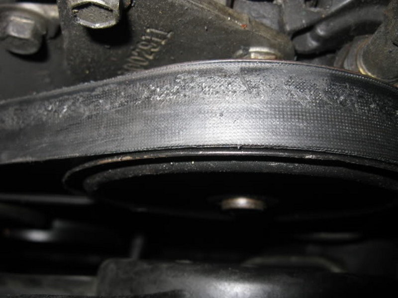
Figure 1. A worn serpentine belt. 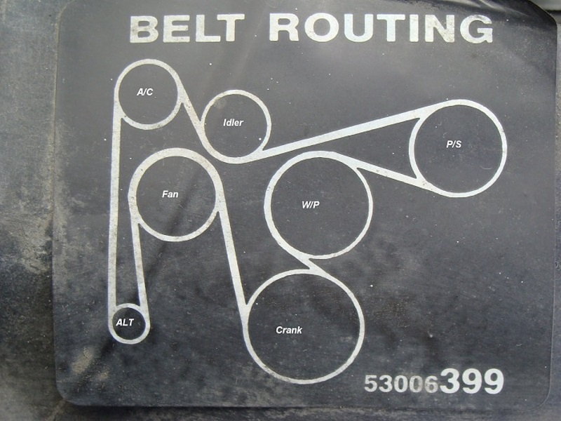
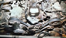
Figure 2. Serpentine belt routing. 
Figure 3. The serpentine belt routing on a 1999 Cherokee.
Step 2 – Inspect the belt while the engine is running
Start the engine and keep it at idle. Follow the belt along its path around the accessory pulleys, listening for any squeals. This noise is related to belt slip caused by stretching, or dirt/fluids interacting with the belt. Make sure the belt is not riding partially off one of the pulleys.
Look at the pulleys as they rotate. There should not be any wobbling. If there is, the pulley may be bent or incorrectly torqued. Bearings inside the pulley's shaft can cause this also. A mechanic's stethoscope can be used to amplify the bearing noise. Grinding and rattling may be heard if the bearings are damaged badly enough.
Repeat the inspection with the RPM raised to about 2,000. Snap the throttle wide open several times and record the results.

Pro Tip
Inner fender liners and splash shields below the engine protect the serpentine belt from dirt. Make sure they're installed correctly.
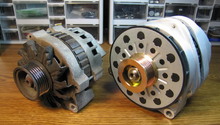
Step 3 – Re-tension the serpentine belt
The serpentine belt is tensioned by adjusting the position of the power steering pump. On the front and back of the pump are five different attachment bolts. Below the power steering pump pulley is a nut that rides along a groove on the pump's bracket. On the right side of the pump bracket is another bolt that adjusts the tension on the belt based on how much it's loosened or tightened.
Loosen the attachment bolts and the nut in the pump bracket groove, just enough for the pump to rotate.
Turn the adjustment bolt clockwise to create more belt tension. Once the desired amount of tension is reached, tighten the adjustment nut and then the attachment bolts.

Figure 5. The attachment bolts are circled in blue and the adjustment bolts in red. 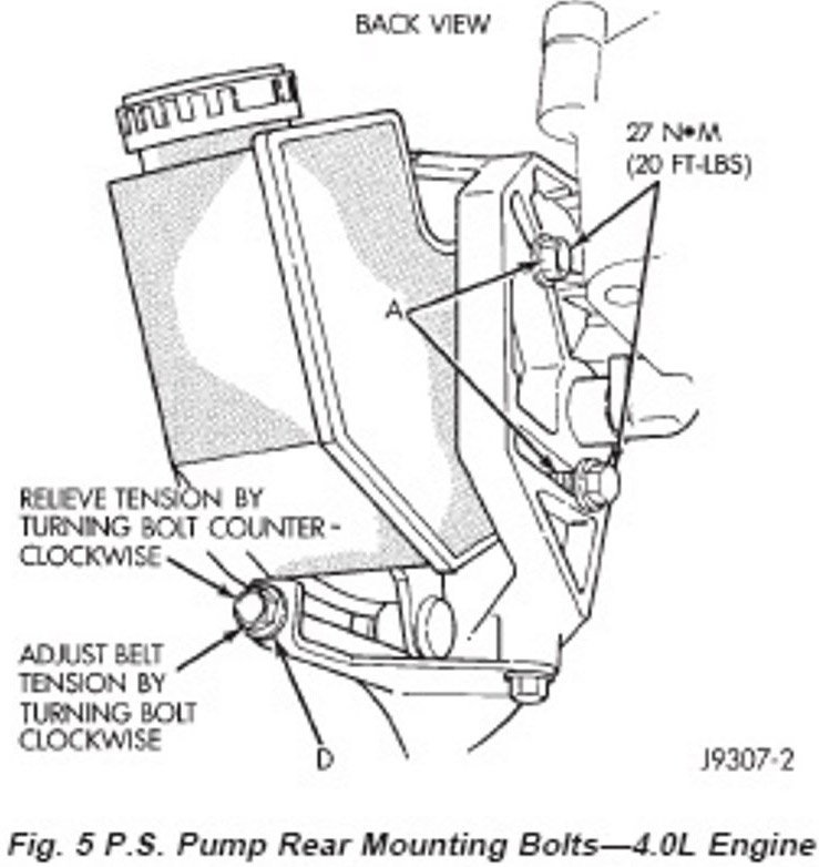
Figure 6. A diagram of the power steering pump.
Related Discussions
- Why is My Belt Slipping? - CherokeeForum.com
- Slipping Belt - CherokeeForum.com
- Serpentine Belt Squeal - CherokeeForum.com