Jeep Grand Cherokee 1993-2004: Why Does My Fuel Pump Not Work?
The fuel pump is submerged in the fuel tank, supplying the engine with the gasoline it needs to run. The pump is powered by electricity from the battery. A combination of fuses, relays, and wiring are used to control the fuel pump's operation for multiple purposes on your Jeep.
This article applies to the Jeep Grand Cherokee ZJ/WJ (1993-2004).
When the ignition is switched to the "on" position, the fuel pump creates pressure throughout the fuel system. This results in a atomized spray of fuel into the engine from the fuel injectors. The fuel pump receives battery power from the fuel pump relay. Once the relay is energized, voltage is sent to the fuel pumps electric motor, which turns the pump. The pumps rapid rotation is often heard as a buzzing sound coming from the fuel tank. Fuel pump replacement is not easy on the Jeep Grand Cherokee, making a definitive diagnostic process very useful when used beforehand.
Materials Needed
- Multimeter
- Flashlight
- Jumper wires
- Zip ties
- Diagonal cutters
- Electrical load (5 amp) for testing
- Electrical connector/terminal cleaner
Start your diagnosis by checking for OBD trouble codes.
Step 1 – Perform a preliminary inspection
When you turn the key to the "on" position, the fuel pump should prime the fuel system for several seconds. You can hear the buzzing sound the fuel pump makes by removing the gas cap and listening through the opening. No sound indicates the fuel pump is not be powered on. If the pump is powering, you may want to try adding a fresh tank of gas. Look under the vehicle for liquid landing onto the ground. This may be fuel leaking from your tank, feed, or return line depending on the leaks location.
If your problem also includes a light that displays a circle with a key inside, you may have SKIS (security system) malfunction. This system will shut down the ignition and fuel system until the correct message is received from the vehicle key. Inside the key is a chip that communicates a code with the transponder. You may also notice that none or some of the gauges in the instrument cluster do not work.
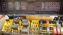
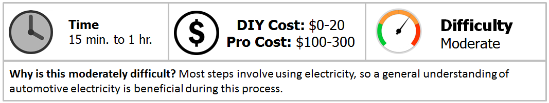
Move to the power distribution center in the engine bay. This is where the relays and fuses and stored that apply to fuel pump operation. Check fuses f6, f2, f15, and f3. You will see a diagram of the fuse locations on the inner side of the P.D.C cover. Use a flashlight to look inside the fuse. You will see a metal strip. If the strip appears dark or broken, replace it. A continuity test can be done with a multimeter, as well. Place one lead on each end of the fuse with the multimeter in the continuity position.
Locate the C1 connector at the engine computer. You will find this connector on the side below the white sticker. This connector has been known to become loose, causing intermittent starting and no starts. Tie a zip tie tightly around this connector to keep it pressed firmly against the computer.
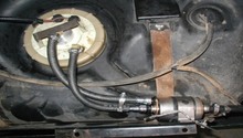
On the underside of the vehicle, in front of the gas tank, is the four wire fuel pump assembly connector. Look for any damage to the wiring around the connectors. Separate the connector by pushing on the red locking tab and squeezing the flexible tab while pulling the connectors apart. Look for corrosion inside and clean the connectors with terminal cleaner. Firmly press them back together until a click is heard.
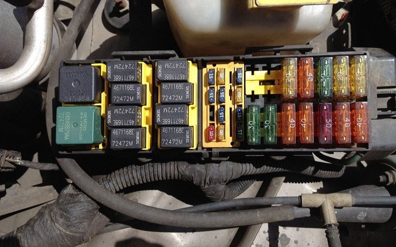
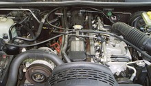
Figure 1. The power distribution center located near the battery. 
Figure 2. The engine computer connectors have been zip tied. 
Figure 3. The fuel pump assembly connector.
If the pump is not powering on, continue with this step.
Step 2 – Test relays between battery and fuel pump
Find the fuel pump relay in the power distribution center. You will see a diagram on top of the relay. Remove the relay by pulling it upward. Use a small piece of wire with connections on the end that fit inside of the P.D.C. These can be terminal clips or connections designed for probing. Connect one end of the wire to terminal 87 and the other to terminal 30. This supplies battery voltage to the fuel pump. If the pump now runs, the fuel pump relay will need to be replaced.
Another relay that powers the fuel pump is the A.S.D. (auto shut-down). This relay cuts power to the fuel and ignition system in the event of a security system malfunction. You can test this relay by removing it (refer to the bottom side of the P.D.C. cover for its location) and attaching each end of the relay coil to the battery's positive as well as negative terminals. You should hear the relay click. Now, test for continuity between the relay switch terminals. If the relay does not click or continuity is not present at the switch, replace the relay.
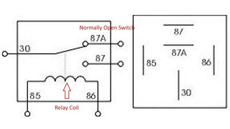
Figure 4. This relay's switch moves to terminal 87 once the coil becomes energized. 
Figure 5. Jumping two relay terminals with a jumper wire.
Step 3 – Check fuel pump assembly
Using an extra battery (similar to an automotive battery) or the battery installed on your jeep, route two wires to the disconnected fuel pump assembly connector. Attach one wire to each battery terminal. Connect the other end of the positive wire to the green/black wire. You can use a small probe to reach into the connector for electrical contact, or strip some of the wiring insulation back. Attach the ground wire to the black wire and listen for your pump to run. If no sound is heard, the pump is most likely in need of replacement. There is a small possibility the wiring from the connector to the fuel pump is damaged or the connector at the tank is not making proper contact. Check for continuity between both wires from the tank up to the connector in front of the tank. You will need to lower the tank to reach the wiring up to the fuel pump.
The continuity check is a good test, but not completely decisive. You will need to apply a load onto the circuit similar to the fuel pumps (about five amps) to rule out the chance of a damaged/corroded section of wiring being present. A properly sized light bulb that draws five amps or an electric motor make for a useful diagnostic tool. Attach one end of the fuel pump circuits wiring to the load and the other to the battery. If the load operates as designed, you can be much more certain the wiring is not your problem.
Continue with Step 4 if the pump will run with battery power supplied.
Step 4 – Check ground wire
The ground wire for the fuel pump is located behind the driver's side trim panel. It is ground number G302 on most wiring diagrams. Once the trim panels are removed, inspect the ground for a clean, secure connection to the body. You can load test the ground using the test described in Step 3 to verify if it's capable of flowing current. Apply power from the vehicle battery to the ground wire and measure the voltage after the electrical load on the ground side. The ground side of the circuit should have less than 100 milli-volts to qualify as a good ground.

Step 5 – Locate the wiring problem
If you've discovered your fuel pump, fuses, relays, and ground and not the problem, you have a wiring problem somewhere in the circuit. This could be an intermittent short to ground for example; although, these are usually accompanied by blown fuses. You will need to pick an easy to access centralized spot in the circuit, then probe the power, and/or ground wire(s) using the load testing method. Continue applying power and ground on positive and negative sides of the circuit independently until the affected area of the circuit is located. A properly operating circuit should show 12 volts up to the load and less than 100 mill-volts after the load.
Related Discussions
- No Power with New Fuel Pump - CherokeeForum.com
- Please Help, Need Advice on Jeep - CherokeeForum.com
- Fuel Pump or PCM - CherokeeForum.com