When you click on links to various merchants on this site and make a purchase, this can result in this site earning a commission. Affiliate programs and affiliations include, but are not limited to, the eBay Partner Network.
When I initially pulled this project together I knew I needed an additional power distribution panel for my lights, triple e-fan setup, subwoofer...
I went and did the unforgivable and cheaped out.The unit I got was rated for 80 amps total and had few connections all rated at 30 amp a piece. Therefore, I had all 3 spal fans going thru one relay and one fuse.
It melted everything!
Even though it never blew a fuse.
Of course I vowed never to allow that to happen again. So here's my remedy.
I used this link http://www.bodenzord.com/archives/473 as a guide but did not agree with the use of one bus for grounding. I chose to stick with using switched power on one bus and unswitched on the other (80 amps each).
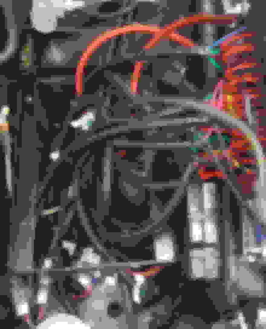
I used 4 relays for headlights (Left Lo, Left Hi, Right Lo, Right Hi) each on its own fuse. Overkill I know. I also used one relay for each fan plus one more for a kill switch. I ran the ground of the solenoid for each of the three fans to the normally closed 87a on a fourth relay. Throwing the switch kills all three fans even though using separate temp switches. Center fan is controlled by AUX circuit from ECM and two outer fans by accessory temp switch (more on that later). Lastly Lite Bar and Fog light relays.
Some that just happened to fall into place is I can rest panel in slot between ECM and fender wall and it stays nicely in place while I play with wires.
In the lower left you can see the 80 amp continuous relay for the switched side of the PDC. The 4 ga wire from CE Electronics runs under the radiator back to 80 mega fuse panels behind battery. The Bussman 200 amp relay is for the winch. I hated the one that came with the winch.
and here it is with the panel in place.
Now back to that accessory fan switch. I feel like I'm in the twilight Zone. Every option for adding an additional temp switch is for a 1/8 npt switch but there's like nothing out there and certainly nothing in the right temp range. Why are they making inline rad hose adapters with only /8 npt holes when there's nothing for them
Nice wiring though! I really want to eliminate my belt driven fan and move to an e-fan setup but that's probably going to have to wait until I finish suspension mods (and new bumpers, and tires....)
In the original, melted setup were the relays protected (internally or externally) via diode or resistor?
Can someone verify if the fan motors keep spinning after the power is shutoff and that voltage generated needs a path to ground otherwise it will degrade the contacts inside the relay.?
I've been over designing my harness for the past few months and haven't made up my mind on relays. A surge protection device manufacturer rep and I had a nice convo about protected relays and he highly recommended a diode based relay over a resistor.
Not sure if this helps, but have you looked into the Volvo fan relays I'm pretty sure they should work for what you're talking about.
In the original, melted setup were the relays protected (internally or externally) via diode or resistor?
Can someone verify if the fan motors keep spinning after the power is shutoff and that voltage generated needs a path to ground otherwise it will degrade the contacts inside the relay.?
I've been over designing my harness for the past few months and haven't made up my mind on relays. A surge protection device manufacturer rep and I had a nice convo about protected relays and he highly recommended a diode based relay over a resistor.
No they weren't!
The new setup is but didn't give that a consideration on the old setup. What I saw was that the load wire from the relay was getting hot right were the wire connected to the relay. It was bundled with other wires and as that 12ga wire heated up it melted the plastic and other wires in the bundle finally creating a massive short.
My assumption was that on hot days when the fans were cycling constantly the start amps which is different than running amps was continuously causing the wire to heat but not blow fuse because it was momentary.
I never considered the fans turning into generators from free wheeling. Doesn't like it would be enough to create that much heat.