When you click on links to various merchants on this site and make a purchase, this can result in this site earning a commission. Affiliate programs and affiliations include, but are not limited to, the eBay Partner Network.
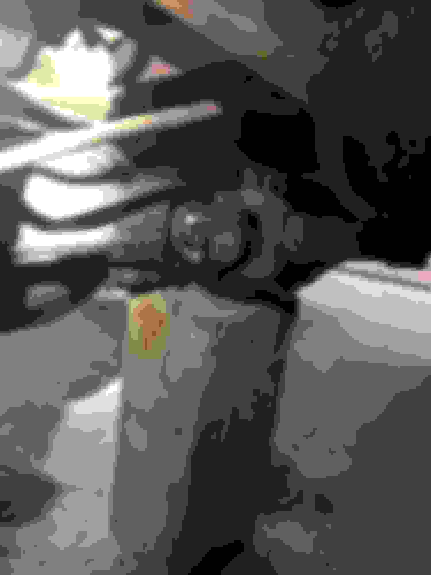
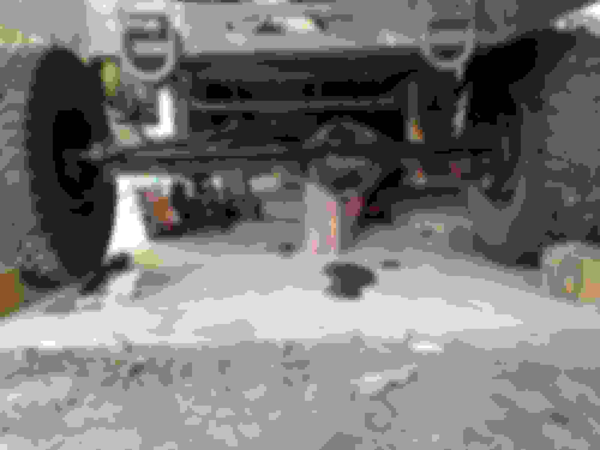
yup. drive shaft cap is seated properly on the passenger side, but if you look closely at the drivers side, it is sitting on the cap tab. the ujoint should be sitting in the yoke better so the cap tab can stop it from sliding out.
look closely at the pics to see what we mean.
otherwise, great job. i have the same axles and will be doing the same thing to one of my xj's.
Just to make everyone aware, in the pictures the drive shaft isn't set right cuase I was still playing with the pinion angle.
Thanks for everyone catching it though, makes me feel good about the rest.
Steering looks good to me. What's the caster going to work out to be? Set that yet?
To be honest, it's going to be one of those it is what it is things...
I didn't cut the C's off to change it, I'm running 4 degree bushings and adjusted the pinion angle to what looks to be good. So we'll see how lucky I am...
I do have threaded Hiems so I'll be able to tweak it some.
If it doesn't work out I'm going with plan B. Knock off both C's and narrow to waggy width.
Last edited by Desertfox1023; Sep 22, 2014 at 10:30 AM.
I almost asked you if you wanted me to cut that broken bolt out of the arm but forgot. I'll have an update for you tomorrow on the status of the arms and an ETA of when youll have them back.
I almost asked you if you wanted me to cut that broken bolt out of the arm but forgot. I'll have an update for you tomorrow on the status of the arms and an ETA of when youll have them back.
Awesome, I won't complain if the bolts out when I get them back... I been trying to think of the best way to do it.
When the guy did the plating it sticks out to far and that bolt is wedged against it. I bought the tap for the holes and I'm going to chase all the holes so I don't have that problem when I go to bolt them together.
My thoughts were to cut the bolt. This then lets the end that wedged against the arm fall off and hopfully just hand thread the rest out.
Yep my thoughts as well. If it won't hand thread out I was going to use an extractor.
Update:
1) I cut the back off the Bolt with a cut off wheel
2) Drilled a Center hole for the Extractor
3) Drilled a Bigger Hole for a Bigger Extractor
4) Tried to turn it with a pipe wrench
5) Applied some heat, came right out.
Last edited by Desertfox1023; Sep 30, 2014 at 07:07 AM.
Thought I was going to have to get the new arm reemed out, but it appears it already has the correct taper.
I have an update on this:
While the taper is the same on the tie rod I had previously. The taper depth is different. Therefore if you want a bolt up Tie Rod End for the Waggy Drop Pitman Arm use part number #ES 2234
good job. but why the bend in the arms? will they not contact the floor on up travel?
i only ask this cause i will be extending the radius arms for my build to reach my long arm cross member, but never considered a bend.
how much of the original ford radius arm did you leave and what did you use to weld them together?