When you click on links to various merchants on this site and make a purchase, this can result in this site earning a commission. Affiliate programs and affiliations include, but are not limited to, the eBay Partner Network.
Hey, hey, hey! I feel like we never talk anymore... Recently I have been having trouble finding time to work on the Jeep. However, I am on vacation this week between my internship and school and the weather has been gorgeous! I've spent the past couple days playing with the Jeep. At the place I am currently living I can't really do much of the heavy cutting and welding I need to be doing but I have been taking this opportunity to resolve some long standing minor issues. For some reason I have had motivation to redo a ton of wiring that I have done over the past few years to clean it up and fix some things that haven't worked in awhile. I haven't made any changes to the operation of the Jeep but I've spent the last 2 days upside-down with my head under the dashboard making things look nice.
The most time consuming part was going through my aftermarket alarm/remote start/keyless entry unit. A bit of a peculiar situation with it. Several weeks ago I spent a few days diagnosing and repairing my power locks. They have worked since. Two days ago I ripped apart a bunch of wiring on my Python 1400xp alarm/remote start/keyless entry unit to solder connections that the installer just twisted together, as well as hard-mount the unit and run the wiring nicely. That morning I used my key fob to unlock the doors before messing with the wires. When I was finished the power locks would not work. I could hear the relay triggering in the door but the locks wouldn't actuate. I assumed that I had done something to cause the locks not to work so I spent almost 3 hours going back through everything I did as well as the owners manual of the Python to review wiring schematics and programming sequences. After not getting anywhere with that I changed course and focused on the locks circuit. A step I never did when repairing the locks previously was re-soldering the connections on the door switches, which can cause the symptom I was experiencing. I pulled the switches and re-soldered the connections and wa-la! They worked. I thought it was very interesting that the switch failed after I was messing with a different part of the circuit. I was getting very frustrated after awhile of not finding anything but it felt great to get those working again.
This picture shows what I have been dealing with for the past couple days. Picture me upside-down in the Jeep with a headlamp on in the middle of the day in my driveway at the beach. My neighbors must think I'm crazy.
I don't have an after picture but I made all of the wiring under there neat and tidy, as well as hard mounted the OEM connectors in their original locations.
Day two I focused more on repairing accessory wiring that I have done. I rewiring my trans-temp gauge, subwoofer remote switch, CB radio, fog light switch and sunroof. During this process I got a bit carried away and ending up doing something I had no intentions of doing when I started: making a custom 5-switch bezel from the multiple 3-switch bezels I have had laying around for years!
I wanted to do this to better utilize the space on my dash. I intend to use the 2 new switches for extended idle and an aux fan override.
I started by cutting the bezels into the pieces shown below. I used a hacksaw blade in my hand (which actually worked well) and sandpaper/a file to get the fit just right.
My original plan was to join the pieces with JB weld but my soldering iron was already hot and right in front of me. I said "I wonder.." and tried plastic welding them with the iron. It was an absolute success.
A bit of sanding to clean up the seams and this is my finished product! I was careful not to be too rough with it but I tried twisting and bending it a bit and it seems plenty strong enough.
I also had to modify some switches. The three factory switches (rear defrost, rear wiper, fog lights) all operate different. Rear wiper is 3-way switch with the 3rd position springing back to the 2nd position. The rear defrost and fog light switches are both 2-way but the defrost springs back to the 1st position whereas the fog light remains in the 2nd position until it is switched back. I need 2 position switches and wanted them to operate like the fog lights but I did not have any spare fog light switches that work (that's why I had 3 bezels in the first place; I was looking for a functional fog light switch). So I modified the defroster switches by removing the internal spring that pushes it back into the 1st position, allowing them to operate just like the fog light switches.
I also had to remove this ridge on the side of one of the switches to allow it to fit into the bezel. Each of the ports in the bezels are keyed such that each switch only fits in one spot (shown below). I simply cut the ridge off and it fit right in.
So that was fun! Only problem is I didn't think to get the switch connectors when pulling these bezels so I need to go back to the junkyard to get some.
Moving on: I had it in my head that I wanted to wire my sunroof into my junction block (fuse box by passengers feet). There are 3 spare fuse slots that are wired with 12 awg leads. Two are switched and one is constant. Looking at my FSM wiring schematics it seems as if the fuses are powered but there is no downstream wiring from the fuse. They each are shown as being wiring to connector C4 but do not have pin numbers called out. This lead me to believe they are not wired to the connector. I did not think it was worth attempting to put new pins in the connector so I opted to use fuse taps in the spare fuse locations for the sunroof leads. Previously I had them wired into my cigar lighter and power outlet but I would like to have them on dedicated circuits.
Without my cigar lighter I now have an unused 25 A circuit. I'm thinking it will be perfect for heated seats, if I ever get to that.
The next big step I'm looking to do in the near future is to clean up the wiring under the hood. Currently it looks like a rat's nest. I want to move my headlights/foglights/fan override and other accessories into the PDC, as well as fill in all empty locations with terminals for future projects.
Its all about practice! That's how I've been treating all of my time doing this. I don't mind taking the time to really work my way through these things thoroughly because I am learning and getting much better at it. I've been enjoying the process of learning.
I had to ground down one of those guides too when I started with my Ext Idle switch install. Picked a 4 slot one form England and the fog light switch and Ext Idle switch wanted to both share the third position. Good to know that you can modify guts in switches to make them do different things.
What are you using for reference guides on electrical issues?
The most important tool for diagnosing electrical issues is a year specific factory service manual. It is absolutely invaluable because it shows every circuit on the vehicle including wire colors but also gives descriptions of how systems are supposed to operate. An example is the power locks circuit. There are intricacies about the locks system that I was unaware of that I would not have been able to diagnose had I not had access to the manual. Did you know you cannot lock the doors from the driver's side switch if the driver's door is open or if they key is in the ignition?
As far as the act of diagnosing electrical problems, that is where the practice has came in. Its not exactly a subject you can watch some videos on and become competent in, I've picked up some great pointers from people here on the forums and have taken some electrical engineering classes which has given me some understanding of how circuits work (voltage is equal to amperage multiplied by resistance). I can't tell you how many times I've spent hours chasing ghosts only to find that the issue was something very minor that I overlooked that could've and should've found quickly. Its all about being patient and methodical.
Thanks! Yeah I have the FSM. I have been looking through that but sometimes they say to check the circuit but they don't explain on how to do that.
You know how to use a multi-meter/test light? Section 8W is a goldmine in the FSM but it takes some time to learn how to use it.
Typically the process goes:
-Check for 12 V at connector --> If no power then issue is upstream of connector.
-Check for continuity between ground and connector --> If no ground then most likely a broken wire.
-Check for continuity across electrical component --> If no continuity then component is junk.
Just as an example. Obviously there are many different situations.
again thank you! I've been looking at youtube videos on the multi-meter. Test light is just sticking it in the wire/connector and if the light comes on then the power is there, right?
again thank you! I've been looking at youtube videos on the multi-meter. Test light is just sticking it in the wire/connector and if the light comes on then the power is there, right?
Essentially, yes but there are some intricacies that come along with it.
12 volt circuits are analogous to flowing water. Voltage is pressure, amperage is volumetric flow rate and resistance is still resistance (friction, small pipe, etc). When measuring voltage you touch one probe of the meter to the point you're trying to measure and the other side to ground. The reason you touch the other side to ground is because the meter is measuring the "pressure" that electrons are trying to push through the meter into ground. The meter needs the ground as the reference of zero voltage (pressure).
When measuring resistance (which has the unit of "ohms") you are taking a measurement of how difficult it is for electrons to pass through the medium. There is no medium which exhibits zero resistance or infinite resistance, meaning that electrons can and will pass through anything in response to a voltage but will always experience a loss in energy (aka pressure, aka voltage!) due to resistance. This energy is transformed into heat which is radiated into the surroundings. Resistance is measured by a multimeter by applying a known current and measuring the voltage between the two probes, allowing the meter to determine resistance with Ohm's law (V=i*R).
A circuit is said to have "continuity" when there is very low resistance from beginning to end (such as a wire in good condition). When somebody says "test for continuity" they are saying to measure resistance between two points in a circuit. Typical values you may see are 1-5 ohms for a circuit in good condition. A "short circuit" is when the circuit makes continuity to ground somewhere where it is not supposed to, such as if insulation on a wire has been rubbed off and the bare wire is touching something that is grounded. An "open circuit" is when the circuit has very high resistance, sometimes approaching infinite, which indicates there is a broken wire or connection somewhere and the electrons have essentially hit a wall that is very difficult to overcome.
In a 12 volt circuit the amperage that flows is controlled by the resistance seen. A 5 amp circuit will have 10 times the resistance of a 50 amp because Ohm's law says the product of each must equal 12 volts in both cases. This can cause some trouble with short circuits though. Imagine a wire that shorts to ground close to the battery. This will have a very small resistance, allowing the voltage to push a very high amperage through the wire. At some point the "friction" of the electrons passing through the wire creates enough heat that the wire will melt and potentially catch on fire. That is why we put fuses in circuits very close to the voltage source. Fuses are in place to protect the wires, not the component!
Keep readin, keep learnin.
Last edited by XJlimitedx99; Aug 25, 2018 at 07:15 PM.
So, do I have something for you guys! The past few days have been quite the eye-opener for me regarding my little project of adding circuits to the PDC. Long story short, I got in way over my head for the amount of time I have and had to retreat, for now.
My goal is to fill my PDC to eliminate my rats nest as well as make adding circuits very easy in the future. This is what it currently looks like under my hood and in my PDC:
I first want to add my low beam, high beam, and fog light circuits to the box, as well as rewire the aux fan circuit to be on an override switch. I purchased a PDC from someone parting their XJ and tore it down to extract wires with the connectors I need from it. It as also an opportunity to learn how to get them in/out without damaging the small clips that hold them in. That went well enough and I shortly proceeded to tear into my box, ready to start wiring like a ravenous wirer guy. My first thought was to start with the headlight circuit because I thought it will be the most difficult due to the Putco harness already changing the way the circuit is routed. After staring at it for about 10 minutes I decided to save the headlights for last for the same reason of them being the most difficult. .
I quickly realized two things after looking at the underside of my girlfriend's Jeep's box:
1) I did not have nearly enough wires with the proper types of connectors on them to outfit the entire box with terminals. There are four different terminals found in the PDC; mini fuse, maxi fuse, mini relay, maxi relay. My Jeep has three empty mini relay slots which I want to utilize but the sacrificial box only supplied connectors from one mini relay. Furthermore, Many of the wires I do have are pretty small gauge. I'm not interested in attempting to uncrimp the terminals to insert different gauge wires. More terminals were needed.
2) I had no idea what I was doing. I must've spent an hour just staring, thinking, starting something then deciding against it. This project needs to be approached with a plan.
In an effort to delay solving issue number two, I went to the junkyard the next morning to find more mini relay connectors as well as grab some other junk:
I grabbed a box from a 2nd gen XJ as well as one from a Liberty. I was hopeful the connectors on the mini relays in the Liberty box were the same as the XJ and luckily they are. Something I found interesting on the XJ box was it had two banks of mini relays and one of maxis, as opposed to mine which has two banks of maxis and one of minis. That means it has (math) more relays than mine! After tearing these boxes down further I found they are modular in the sense that I can pop the maxi bank out of mine and insert a mini bank:
Ideally, I would like to replace all of my maxi relays with minis, The maxis are rated for 40 A and the minis are 30 A so I'll have to do some figuring of what can go and what has to stay.
As you could imagine, after cannibalizing three PDC's I have a metric butt-load of connectors at my disposal, which means I should be able to make the slickest fuse/relay box east of the Mississippi. I have 146 connectors in total, 61 of which are mini relay connectors. I actually made an excel table of the number of terminals I have with certain gauge wires coming from them. Funny thing is, I still feel restricted by that because of the wire sizes. I have a ton of 18 awg, good amount of 16, some 14, a handful of 12 and a couple 10. I think it will be fine because these leads will only be running to outside the box where I'll be mounting a terminal block and can up the wire size there. **(I'd like to apologize in advance for this picture, but...)**
One possible alternative is trying some other connectors in the box which I could crimp my own wires to. I read on another thread that "GM Packard 56 Series Terminals" will snap into the box with modification. The terminals have a locking tang which needs to be removed to allow a hole for the locking tab on the box to snap into. Some guy said his entire box is done with those connectors.
Moving onto issue number 2; I need to know what exactly I'm trying to do before I get in there. This is strange to me because my usual approach is take apart first, wonder how it goes back together later. I decided the best course of action is to tackle one circuit at a time with a well thought out plan of what components will be used and where things will go. I spent an hour this morning making this wiring diagram for my fog lights/CB radio circuit:
For some reason I decided to do this in the most convoluted way possible. Although, so did Jeep when they made these. Did you know that the amperage of the fog lights flows through the switch, similar to the headlight circuit, but it is actually downstream of the relay? No idea why they would do that. Anyway, instead of running new wires I decided to reuse ones already there (BR/YL, VT, and LB on my diagram) and just change their position/function as necessary. Notice this puts the switch downstream of the relay on the trigger circuit. Unconventional but it should work just the same.
So, after all that, some bad news. It is that time of year again when I'm going back to school. Classes start Monday, which means my Jeep time will be infrequent. I definitely bit off more than I could chew by thinking I could tackle this project in the few days I gave myself but now I understand what I have to do. I tasked myself with creating a diagram similar to the one above for each circuit I plan to add so I know exactly what is going where in the box when the time comes to assemble it all.
I'm pretty stoked to get back to school this year because my senior project is to design and build an FSAE race car. I'm tentatively leading steering and suspension. Should be a hell of an experience.
Last edited by XJlimitedx99; Aug 26, 2018 at 04:39 PM.
Things have been pretty crazy for me this year. The racecar project has been much more of a time commitment than I anticipated. Our competition is in the beginning of May and our car isn’t together yet. Really coming down to the wire. Graduation is right after and I’ll be getting that piece of paper regardless.
After graduation I’ll be moving to the western side of NH to the Keene area for a job at Whelen Engineering as a manufacturing engineer. I’m beyond excited to graduate and start there.
Anyway, 6 months or so ago the Jeep left me on the side of the road. Sputtered, died, and would not start again. I had it towed to my parents house and didn’t mess with it all winter. Yesterday the weather was gorgeous so I trucked back to my parents house for a day of playing with my Jeep.
After charging the battery I tried to start the Jeep and it fired right up as soon as I kissed the key. Ran for about 10 minutes then sputtered and died. Over the course of continuing to run the engine it eventually got to the point of crank no-start.
First thing I did was check my grounds because it seemed like something was failing from getting hot. I found my main ground by the battery was very corroded and barely hanging on, so I redid that. Ended up breaking the bolt and the captive but behind it. Ripped the sheet metal right off. Replaced it with some big washers, a new bolt, a glob of dielectric, and called it good.
That didnt fix the issue so I moved onto what I assumed I needed to do; the CPS. I had ordered a Mopar sensor a few days ago so I already had one on hand. I’ve heard so many horror stories of how bad dong the crank sensor is so I approached this job carefully. I used an 11 mm socket with a 36 inch extension and a unjoint. Talk about sorcery. All in all, once I figured out where to lay so I could see and how to get the socket snaked up in there, it wasn’t that bad. My dad helped by holding the socket/bolts straight by reaching down from the engine bay. That made it way easier.
After doing the sensor everything seems to be operating well. I’m feeling on top of the world after getting that running and driving the Jeep for the first time in 6 months.
A few buds and I have an overlanding style trip planned in June that will snake us up through NH and into Maine up to Moosehead Lake. Gotta get the Jeep whipped into shape for that trip right after graduation. More to come!
Last edited by XJlimitedx99; Jun 2, 2019 at 09:27 PM.
It looks like the grease is oozing out of the connection. Dielectric grease is non-conductive, it is designed to insulate the circuit and ease disassembly. You should assemble the connection and then put the grease on the outside of the connection. One better would be to use Ox-gard, it is a conductive grease that promotes better connections. You can find it in the electrical aisle at the Lowe's.
It looks like the grease is oozing out of the connection. Dielectric grease is non-conductive, it is designed to insulate the circuit and ease disassembly. You should assemble the connection and then put the grease on the outside of the connection. One better would be to use Ox-gard, it is a conductive grease that promotes better connections. You can find it in the electrical aisle at the Lowe's.
Correct saying that dielectric is non-conductive, however, I've been using silicon-based dielectric on pretty much all of my electrical connections for several years and have had no issues with it. From my understanding, any amount of significant contact pressure at a connection is enough to squeeze the grease out because of the grease's low viscosity. The magic pixies only flow where metal touches metal. The grease fills the voids where metal doesn't touch metal (at a surface roughness level). Dielectric has shown to add negligible resistance to circuits when used liberally on connections on low-voltage/low-frequency applications. Now, I would not use dielectric directly on the contacts of a high-voltage connection such as a spark plug because there is a potential for arcing which would lead to carburization of the grease and increase abrasion.
Greases with suspended particles to increase conductance spook me a bit because they could cause shorts across contacts which you do not intend juice to flow across. Although, that is unlikely because the grease used in "conductive" grease compounds is still dielectric (at least all the ones I've seen), they just have the suspended conductive particles. The grease still will show no conduction when probed through a glob of it, but will have lower resistance than typical dielectric when subject to high contact pressure, such as at the contacts of a connector. Here, the particles (typically zinc) tend to remain in the valleys of a rough surface while the grease is mostly pushed out, aiding electrical flow through those areas rather than leaving a micro air gap. One place that wire anti-oxidant compound is intended for is aluminum connections. Something about the zinc helps get through the aluminum oxide? Idk, I just work here.
Last edited by XJlimitedx99; Apr 28, 2019 at 10:32 PM.
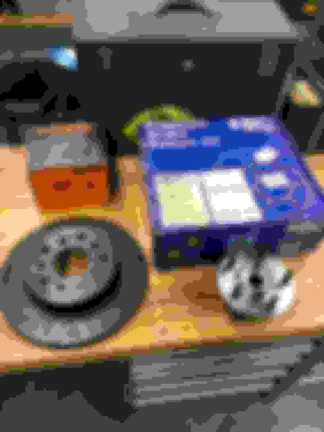
Did a fun little thing yesterday; drilled my rotors out for my WJ swap! I set them up on the mill at school and had them done in a jiffy. I put 39/64 holes on a 2.260" radius which fit like a glove.


 .
.