
Testing the downstream o2 sensor.


Thread Starter
Senior Member
Joined: Feb 2012
Posts: 905
Likes: 8
From: New Hampshire
Year: 1998
Model: Cherokee
Engine: 4.0L I6
So im kinda in a crappy situation here. Somehow the plastic fixture keeping the downstream o2 sensor wires came loose and caused the o2 sensor wires to dangle in the breeze. Of course I didnt know it until the wires on the harness (engine side) had been rubbed through. The wires to the o2 sensor are fine. The downstream sensor is only about six months old as well.
Now I thought I did a damn good job butting the cut wires together but now im getting a code for the downstream o2 heater. So to test my work and avoid possibly buying a new o2 sensor, I went out and bought a fancy new multimeter (I thought it would be good to have one anyways). Im not to educated on using one however. Id like to test my work on the harness before I go ripping all my tape and wire butt connectors off but dont know what to test, how to test it, or what readings I should be looking for.
Any thoughts?

CF Veteran
Joined: Aug 2011
Posts: 10,489
Likes: 24
From: Nor-Cal Coast
Year: 90,84
Model: Cherokee
Engine: 4.0,2.5
You might do a little research. I believe it has it's own relay, (the heater), and a fuse as well. The heater will take about 12V, (one wire). If that grounded while getting mangled it may have blown a fuse. (actually I thought if that grounds/blows it takes out other stuff as well) (ASD).
So, cold at least, you should see that 12 on one wire, and it will need ground on another. (the others would be the 5V fed from the PCM and last the "signal" wire to the PCM.) If I have that right. (some might cut power to the 02 heater when it's hot)
For what it's worth, I once measured 12 Ohm's resistance (to ground), on my 90's only 02 sensor heater wire. It worked, got hot.
CF Veteran
Joined: Aug 2011
Posts: 10,489
Likes: 24
From: Nor-Cal Coast
Year: 90,84
Model: Cherokee
Engine: 4.0,2.5
X2 ^. Slide shrink tube up the wire before you solder, then when it cools slide the shrink tube back and heat it. A wire nut makes a decent temporary connection until it can be done right. (your house has 100 of them)
Thread Starter
Senior Member
Joined: Feb 2012
Posts: 905
Likes: 8
From: New Hampshire
Year: 1998
Model: Cherokee
Engine: 4.0L I6
Okay where is the fuse located for the o2 sensor heater?
When im testing the ohms do I want the battery turned on?
When im testing the ohms do I want the battery turned on?
Last edited by KJamesJR; Mar 16, 2014 at 07:14 PM.
CF Veteran
Joined: Aug 2010
Posts: 8,357
Likes: 103
From: Canton, MI
Year: 1999
Model: Cherokee
Engine: 4.0
So im kinda in a crappy situation here. Somehow the plastic fixture keeping the downstream o2 sensor wires came loose and caused the o2 sensor wires to dangle in the breeze. Of course I didnt know it until the wires on the harness (engine side) had been rubbed through. The wires to the o2 sensor are fine. The downstream sensor is only about six months old as well.
Now I thought I did a damn good job butting the cut wires together but now im getting a code for the downstream o2 heater. So to test my work and avoid possibly buying a new o2 sensor, I went out and bought a fancy new multimeter (I thought it would be good to have one anyways). Im not to educated on using one however. Id like to test my work on the harness before I go ripping all my tape and wire butt connectors off but dont know what to test, how to test it, or what readings I should be looking for.
Any thoughts?
Now I thought I did a damn good job butting the cut wires together but now im getting a code for the downstream o2 heater. So to test my work and avoid possibly buying a new o2 sensor, I went out and bought a fancy new multimeter (I thought it would be good to have one anyways). Im not to educated on using one however. Id like to test my work on the harness before I go ripping all my tape and wire butt connectors off but dont know what to test, how to test it, or what readings I should be looking for.
Any thoughts?
If you matched up the wire colors when you butt spliced them together there shouldn't be a problem.
The body harness side of the O2S wires is:
Heater circuit pin 1=Dark Green/White tracer, pin 2=Black
Sensor Ground (at PCM) pin 3=Brown/Yellow tracer.
Sensor Signal (at PCM) pin 4=Tan/White tracer.
FYI: The O2S heater circuit is not polarity sensitive. There's two White wires coming from the O2S for the heater circuit and can be mixed up at connector pins 1 and 2 without a problem. The Signal and Ground wires must match.
Don't rework the butt splices until you check the wire color match up and the fuse in the PDC.
Edit: If you did a good job crimping the butt splices leave them as is; however; if you didn't use heat shrink type butt splices you should tape them up good and encase the wires in split loom.

Last edited by CCKen; Mar 16, 2014 at 07:35 PM.
Trending Topics
CF Veteran
Joined: Aug 2010
Posts: 8,357
Likes: 103
From: Canton, MI
Year: 1999
Model: Cherokee
Engine: 4.0
Thread Starter
Senior Member
Joined: Feb 2012
Posts: 905
Likes: 8
From: New Hampshire
Year: 1998
Model: Cherokee
Engine: 4.0L I6
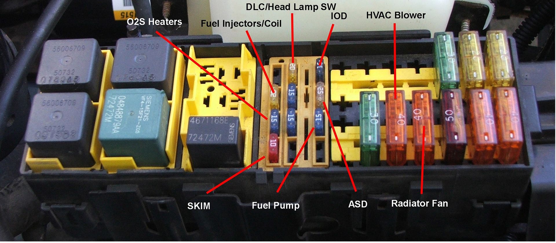
First thing is to check the O2S heaters fuse in the PDC. See pic. THe 98 doesn't have O2S heater relays like the 00/01 XJ's.
If you matched up the wire colors when you butt spliced them together there shouldn't be a problem.
The body harness side of the O2S wires is:
Heater circuit pin 1=Dark Green/White tracer, pin 2=Black
Sensor Ground (at PCM) pin 3=Brown/Yellow tracer.
Sensor Signal (at PCM) pin 4=Tan/White tracer.
FYI: The O2S heater circuit is not polarity sensitive. There's two White wires coming from the O2S for the heater circuit and can be mixed up at connector pins 1 and 2 without a problem. The Signal and Ground wires must match.
Don't rework the butt splices until you check the wire color match up and the fuse in the PDC.
Edit: If you did a good job crimping the butt splices leave them as is; however; if you didn't use heat shrink type butt splices you should tape them up good and encase the wires in split loom.
Now say the fuse isnt blown and I test the resistances at the harness, can I simply use the ground pin (assuming my wiring is correct) or should I find something else to ground it on? If I can get it to test good, I wont have to tear it apart because seriously I used about 3ft of tape, split loom and a ton of zipties.
Thread Starter
Senior Member
Joined: Feb 2012
Posts: 905
Likes: 8
From: New Hampshire
Year: 1998
Model: Cherokee
Engine: 4.0L I6
This was exactly what I was looking for! Thanks again Ken.
Now say the fuse isnt blown and I test the resistances at the harness, can I simply use the ground pin (assuming my wiring is correct) or should I find something else to ground it on? If I can get it to test good, I wont have to tear it apart because seriously I used about 3ft of tape, split loom and a ton of zipties.
Now say the fuse isnt blown and I test the resistances at the harness, can I simply use the ground pin (assuming my wiring is correct) or should I find something else to ground it on? If I can get it to test good, I wont have to tear it apart because seriously I used about 3ft of tape, split loom and a ton of zipties.
CF Veteran
Joined: Aug 2010
Posts: 8,357
Likes: 103
From: Canton, MI
Year: 1999
Model: Cherokee
Engine: 4.0
Thread Starter
Senior Member
Joined: Feb 2012
Posts: 905
Likes: 8
From: New Hampshire
Year: 1998
Model: Cherokee
Engine: 4.0L I6
I did clear the code after doing the job.
I have no wiring diagram nor have I ever used this multimeter before. This will be a learning experience for me as I only have a slight clue of what im doing or what readings I should be getting. Been trying to google it.
Edit: I may have a diagram in my haynes manual.
CF Veteran
Joined: Aug 2010
Posts: 8,357
Likes: 103
From: Canton, MI
Year: 1999
Model: Cherokee
Engine: 4.0
Thread Starter
Senior Member
Joined: Feb 2012
Posts: 905
Likes: 8
From: New Hampshire
Year: 1998
Model: Cherokee
Engine: 4.0L I6