Custom DRL write up
 11-04-2011, 10:22 PM
#1
Junior Member
Thread Starter
Join Date: Aug 2011
Location: Michigan
Posts: 50
Likes: 0
Received 0 Likes
on
0 Posts
Model: Cherokee
Okay, the following is how I created my custom DRLs. They run off power from the fuse box. Note, I am not an advanced person with electrical wiring. Because of this, some of you may find much simpler ways to get these results.
What you will need:
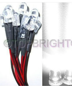
10mm LED bulbs 12V ready (pre-soldered to resistors preferred)
10mm LED bulb housings
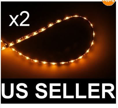
Amber LED strip 2x30cm w/black backing
16-18 gauge wire
Soldering iron
Shrink tubing
Black electrical tape
Liquid electrical tape (optional)
Silicone sealant
8”x10” Lexan sheet
Dremel
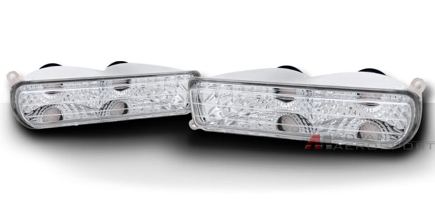
Clear front turn signals
LED load balancers
6V battery (optional, used for testing)
2x Quick release connectors
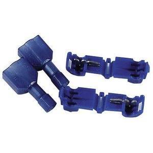
6x T-Tap connectors
Wire loom conduit
Spray primer & black paint
Power drill and �” bit
Thin automotive strength 3M tape from Autozone
Core essentials:
10mm LED bulbs: These can be found in several places, but I found mine on eBay. The ones that I am using have a 140Kmcd candle rating. I own some 280Kmcd bulbs that I purchased a few years ago but did not use, only because I don’t know how to compute the proper resistor needed. The ones I purchased for this project came with resistors already attached. To take the guessing out, I recommend you do the same.
10mm LED bulb holders: I purchased mine 3 years ago when I originally purchased the bulbs I ended up not using. However, I found a website that sells the LED bulb holders, as well as the pre-wired bulbs. I believe this is the same vendor on eBay as well.
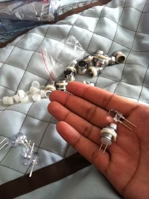
http://www.ledssuperbright.com/10mm-led-c-9
Clear turn signals:
These can be found on eBay and will range from $27 to as much as $40. Sometimes they have them, sometimes they don’t.
2x Amber 30cm LED strip:
These can also be found on eBay and are not required, but highly recommended.. especially if you want a front facing turn signal. Kind of important.
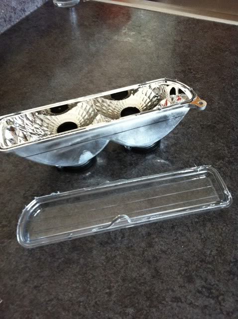
Step 1:(Prepping the clear lens)
Place clear turn signals in the oven on a wooden block at 300 degrees for about 10-12 minutes (or use a heat gun if you have one, I don’t). This process will soften up the adhesive holding the plastic lens to the bulb retaining housing. Remove the block of wood carefully with pot holders or heat gloves and place on kitchen counter. It is not hot enough to cause any burn damage. Pluck out the lens. I used the handle of a standard screwdriver which fit perfectly in the bulb opening. Next, create a �” inch border around the housing with a black permanent marker. The black line will be the area you will cut away during Step 2. When you finish, your clear housings should look like this.
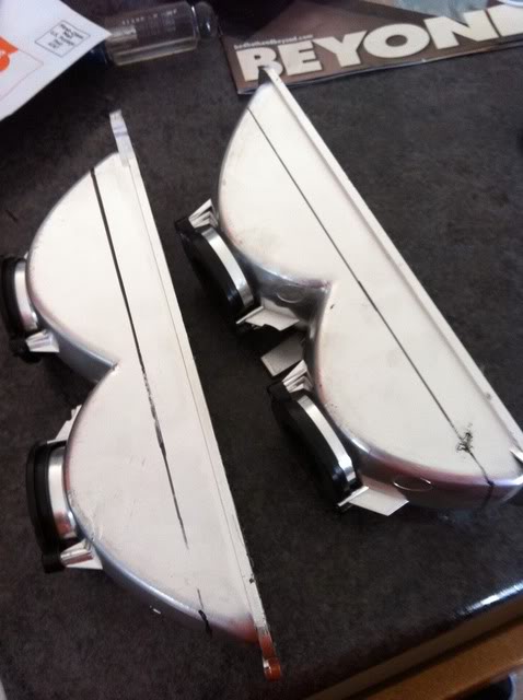
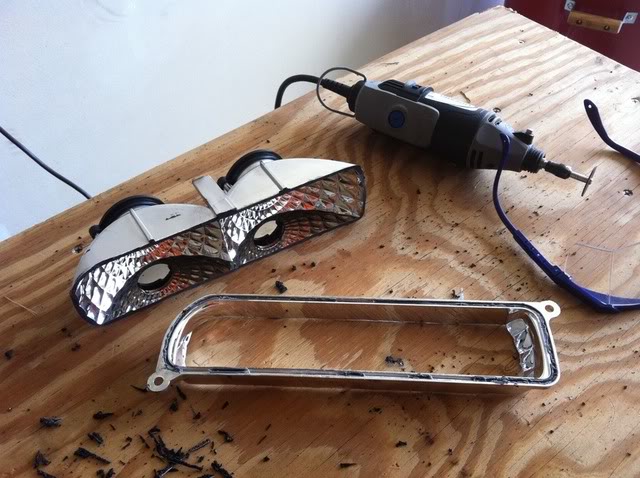
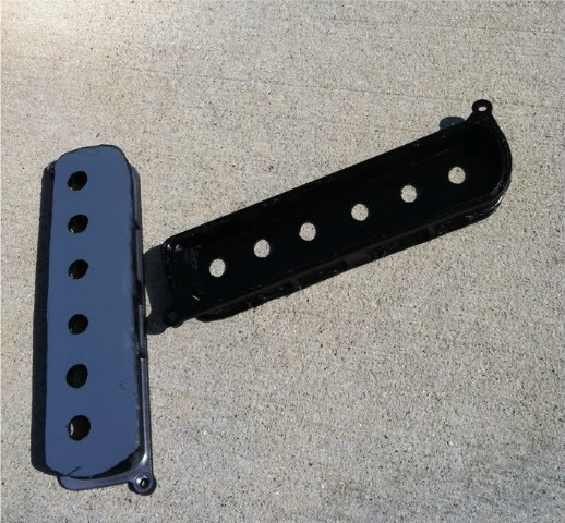
Step 2: (Making the cut)
Grab the bulb housings and leave the clear front alone for now. Head to your garage, basement or wherever you do the most damage during projects. Grab the dremel, the appropriate cutting attachment, your goggles, and I recommend some gloves. Carefully cut at the black line until you end up with two pieces. Make sure you have a tight grip while cutting in case of dremel slippage. At this point, you may discard the bulb backings or save them for a future project. I saved mine for phase 2 of my project. When you finish, each of your signal housings should look like this:
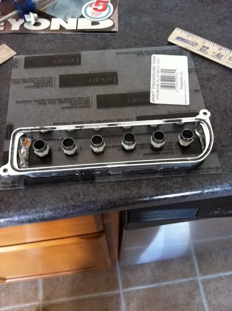
Step 3: (The Lexan) “the lexan sheet was purchased from Home Depot for around $1.50”
Place your cut housing fronts on the lexan sheet and do a rough trace. This does not have to be exact because later, once they are attached, you can dremel away the extra lexan. Line up your 10mm bulb holders and try to evenly space them as best as you can. Do NOT remove the lexan protective sheet because you can use this to draw the frame on and make corrections before you start drilling holes. I recommend drawing a straight line across, then drawing around the bulbs so they are on an even plane. I used six bulbs in each side but it’s up to you how many you want to use. Place the clear cover on top to see how your final project should somewhat look like.
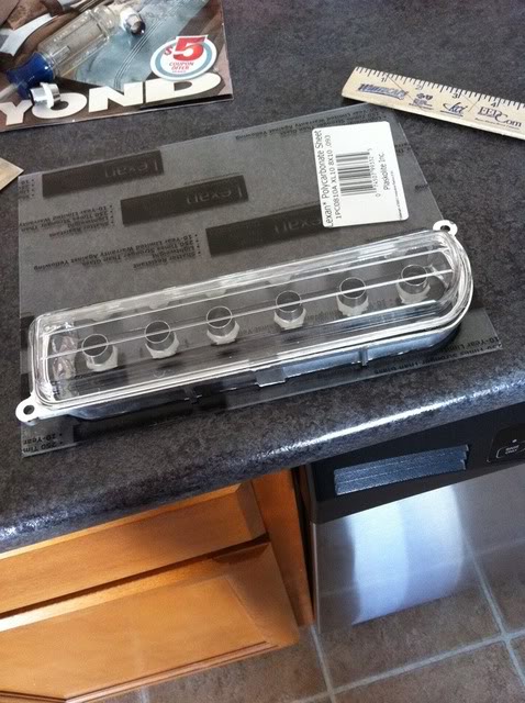
This next part and how you choose to do it is up to you. You can either drill the holes using the �” drill bit now, and then cut out the frame, or you can cut the frame out first, and drill the holes second. I cut the holes first. You may have to slightly enlarge the holes you cut. I used a dremel attachment to adjust the hole size. Remember, you can’t make a hole smaller, only larger so be careful. It does not have to be a snug fit, but you do want your LED bulb holders to cover the hole without having any visible gaps glaring through. Whichever route you take, try not to waste your lexan sheet. You will need to make two housings (one for each side) and you might mess up and need extra lexan to start one side over again. I messed up once, but still ended up having half the lexan sheet left over.

Step 4: (slowly coming together)
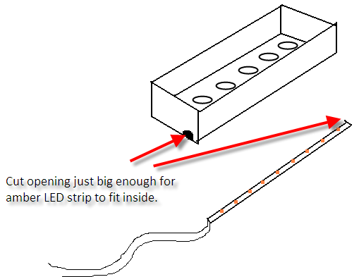
Once you have the bulbs where you want them, remove the bulbs and the bulb holders. I apologize for this next part because I did not take a photo, although it’s kind of important if you are using the amber LED strips. Before you start to permanently attach anything, you will need to cut a slit for the amber LED strip on each side of the DRL housing.
Using the silicone sealant (home depot, couple bucks), attach lexan lens to main DRL housing as shown below. Do not cover up the small hole you just made for the amber LED strip. The silicone I used dried pretty fast, but just to be safe, I did let them sit overnight.
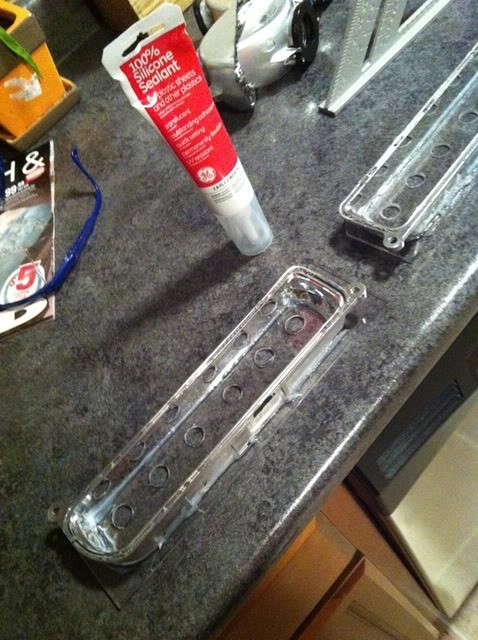
Once the sealant has cured on both of the DRL housings, go back to the garage, basement or wherever and use the dremel to trim down the edges. This is more for visual appeal, but you don’t want the edges extending beyond the edges of the chrome housing.
Step 5 (color me bad)
Now that both your DRL holders are trimmed down and securely fastened, grab the gray primer and spray away. Once they have been primed, you can paint them any color you want. Painting them body color would be kind of cool. The type of paint you use will determine the drying time.
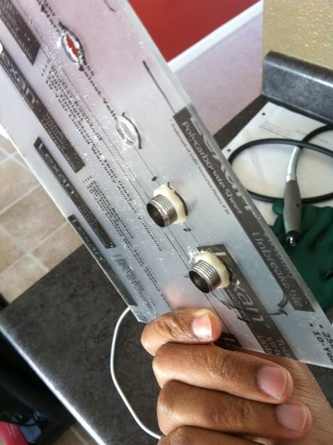
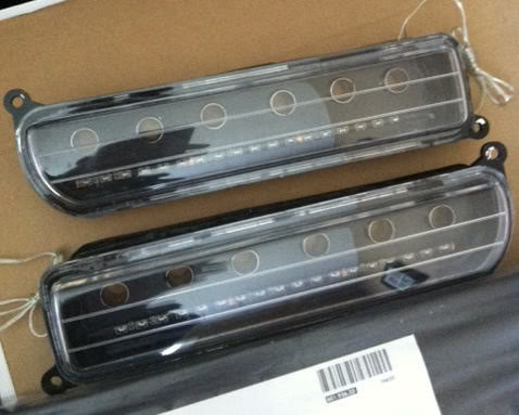
Once your housings have dried, attach the 10mm LED holders but DO NOT attach the 10mm LEDs yet. Next, remove the adhesive backing on your amber LED strips and grab the automotive strength 3M tape and cut a thin strip to reinforce the weak adhesive that your amber LED strips probably came with. You do not want these coming loose once you have sealed the main DRL housing. Slide your amber LEDs through the small opening you cut for each DRL housing. Make sure you press them down firmly so they stay attached and make sure you test them before committing to sealing them.
Note on amber LED strips. You can choose whichever kind looks best to you. I chose the kind that are pretty flexible, but hardly visible when turned off. The kind I chose comes with either a white backing or a black backing. I originally purchased the white, but thought it looked like crap, and purchased black instead, as it looks better with the black housing of the DRL. But to each his own. Below is an example of the white on black, and black on black.
 White background LEDs
 Black background LEDs
Now that the amber LED strips and the 10mm LED bulb holders are in place, use some adhesive on the lens and reattach. I put the lens and the DRL housings back in the oven for 300 degrees to soften up the OEM adhesive. Now that I have finished, I would not recommend doing this unless you reinforce it once it is dried with additional adhesive. Once you pull the bread out of the oven, reattach them then clamp, clamp, and clamp them together for a few hours. The longer, the better.
Step 6: (almost finished)
At this point, your DRL lens should be sealed from the front, and your amber LEDs are sealed inside. Put a dap of silicone over the opening that the amber LEDs was inserted into to water seal that opening. Now you can attach your 10mm LEDs. I used two small drops of hot glue on the back of each bulb to hold them into place. Then I used the silicone sealant to seal each bulb into place.
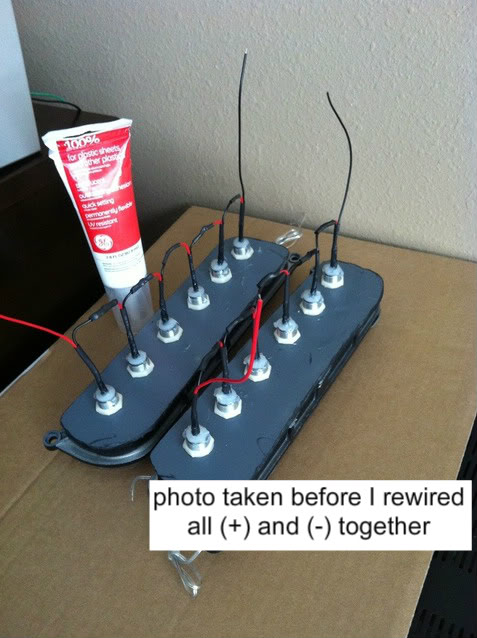
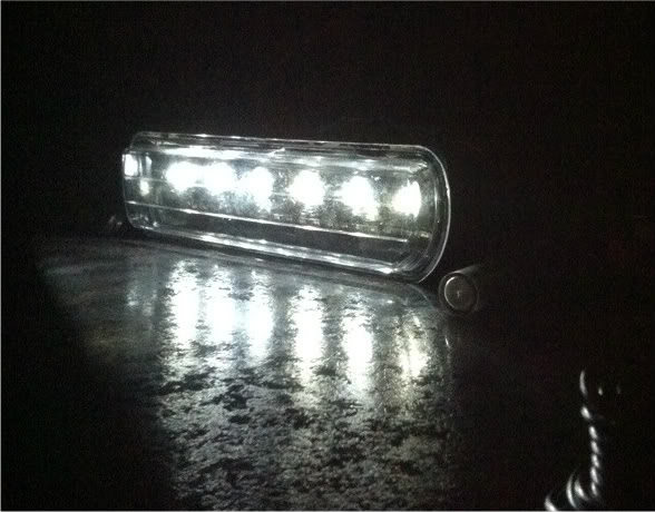
Step 7: (wiring part 1)
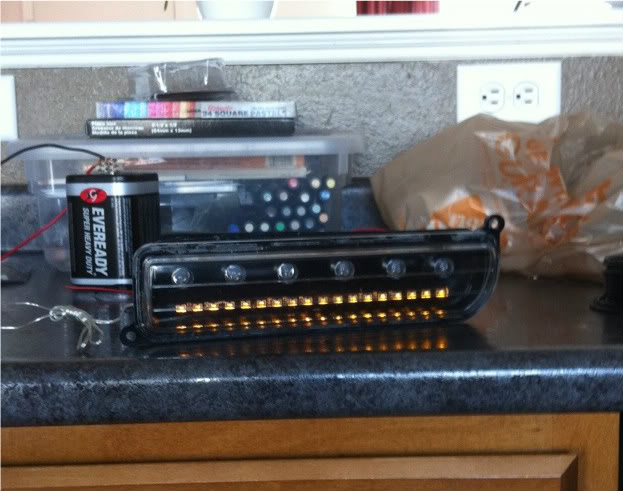
Each of these bulbs have a 12v resistor so we can wire them together in a parallel circuit without worrying about overload or frying of any components. This also ensures each bulb illuminates at its maximum instead of sharing the electric current. Group all the (+) wires together and all the (-) wires together for each side. Use the 6V battery (or another power source) to ensure all bulbs illuminate before soldering or shrink sealing wires together. If you use tape, you can always go back and make adjustments. Kill the lights to see what they are really going to look like. Don’t look directly into them or you will blind yourself.
Step 8 (wiring part 2)
Once you are comfortable with all bulbs working as desired, attach the (+) and the (-) wire clusters to a long (+) and (-) wire. The long wires will be used to run around the engine bay and connect to the power source. The best approach is to create a “T” connection between the long wire, and the 10mm LED wires. Because of the location of the battery on the 2000 Cherokee Sport, the passenger side DRL wiring will need to be much shorter than the driver side so plan accordingly. Finally, give all the wires a solid sealing. They will be somewhat exposed when finished so seal, seal, and seal. But don’t seal too much, because you may need to replace an LED, but hopefully not for a long time. Test the lights again before adding any of the connectors. I picked up the connectors at Home Depot for around $5. You will only need two pair.
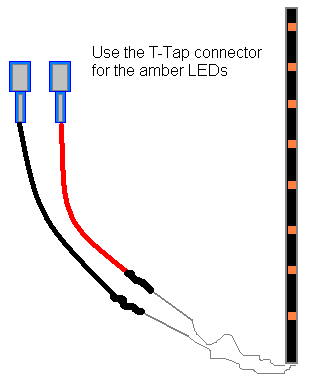
Preparing to run the DRLs with the ignition is easy to do. Preparing to run the amber LEDs with the turn signals however is somewhat daunting. You will need to use some extra pieces of the 16-18 gauge wire and build some wire extensions for the amber LED wiring. The amber LEDs come with some really crappy and weak wiring. Use the T-Tap connector’s male ends and attach to the amber LED wires.
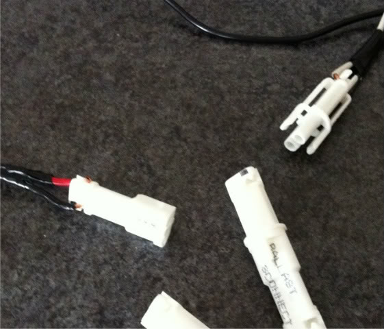
Step 9 (wiring part 3)
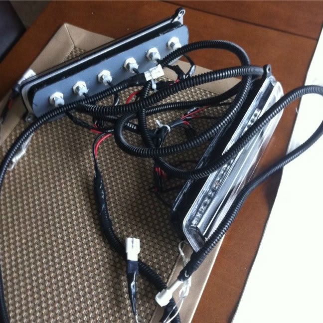
At this point, both the DRL units should have male T-Tap connectors for the amber LEDs and the both DRL units should also have one of the other connectors you purchased. You should use the shrink tubing on these connections. Take the plastic wire loom and wrap the long wires so it looks nice and neat. Tape the ends to ensure the loom does not slide around.
We are almost finished, but now we need to make the power source wiring. You will need to create a positive and a negative wire connection. The length is up to you, but I went with about 18” inches for each. This part will sound tricky. One end power wire connection will only have ONE positive and ONE negative wire. This will be used for the main power and ground of the DRLs.
The OTHER side will need TWO (+) and TWO (-) wires. This can be accomplished using the “T” connection technique as touched on earlier. Okay, here’s how to do it. Take an 8” inch positive wire, strip both ends, then cut around the center with a blade but do not cut the wire. Pull the center apart at the cut until you have about �” or less of exposed wire. Take the 18” inch positive wire and strip about 2” off the end. Take the stripped end and wrap it around the exposed center of the 8” inch wire, then twist the 2” exposed wire around itself. When finished, it should look like a “T” or a “Y” I suppose. Wrap the connected wires with whatever you choose, and do the same for the (-) wire. In the end, you will have your two positive and negative wires on one end, and one (+) and (-) on the other.
Now attach the OPPOSITE connector from what you used for the DRL units to each pair of positive and negatives. You are NOT putting the two reds and two blacks together. ONE (+) and ONE (-) per connector. You will now have somewhere to plug BOTH the DRL units into. Finish by wrapping the power source wiring with the conduit loom but be sure to leave a foot or so unwrapped so that you can extend the positive wire one way, and the negative wire to the battery.
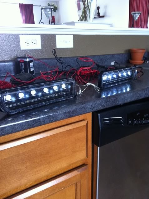
Step 10: (putting it all together)
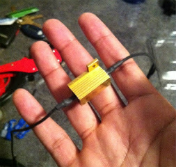
Lay out what you have on the floor. You should have one DRL unit with longer wiring than the other. You should also have your power connection cord created in the last step (not shown in my photo). Also notice I have the big connectors on both my amber LEDs. I know I said to use the T-Tap connectors but just trust me.
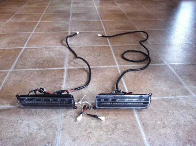
***You should now add the load balancers. I would recommend using T-Tap connectors here as well. These will need to be attached to the amber DRL extension (+) and (-) wires created in Step 8. Without a load balancer, you will get the fast blink / bulb out warning when you use the amber LEDs. LEDs do not demand enough power so the ECU thinks there is a bulb out.
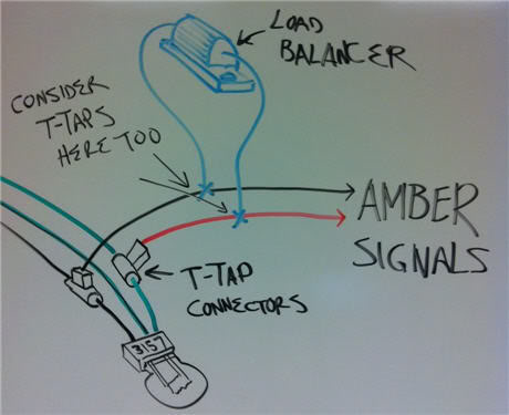
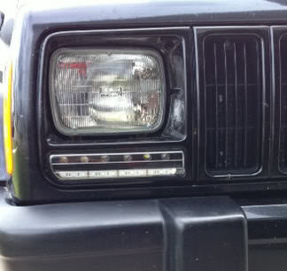
Head out to the Jeep and remove your OEM turn signals (remove headlamp frame first 2 screws, then turn signals…. 2 screws). Pull back one of the 3157 bulb wiring. You want to tap into the ground (black or brown) and the solid green wire (I think). Never rely solely on the splicing connectors so take your box knife and carefully cut a half circular incision around the OEM wire. Bend the wire back and forth a few times to expose the wire under the cut. Take the female end of the T-Tap connector and clamp it over the exposed wire. Now set your DRL unit on the engine bay around and plug in the amber LEDs to OEM wiring. Turn on the vehicle to test using the hazards. Check the regular blinker as well. If it fast blinks, make sure you remembered to attach the load balancers. If you remove the actual 3157 bulb, then it will blink faster than normal, but not rapidly fast. Once you are all set with the amber LEDs, run the long power wires from your DRL unit through the opening under the headlamp and snake around near the battery area. My driver side cord is long enough to skirt near the engine bay body all around.
The million dollar question: What do I do with the OEM 3157’s? There are two on each side, at least with the 2000 Jeep. Well… I will be using one on each side for a future project. The one I tapped into can have the bulb removed, then the housing tucked down somewhere you make room. I purchased bulb covers for mine in the meantime then wrapped the bulb covers in black duct tape so the light won’t bleed through and I won’t get a bulb out warning.
Step 11 (All systems Go)
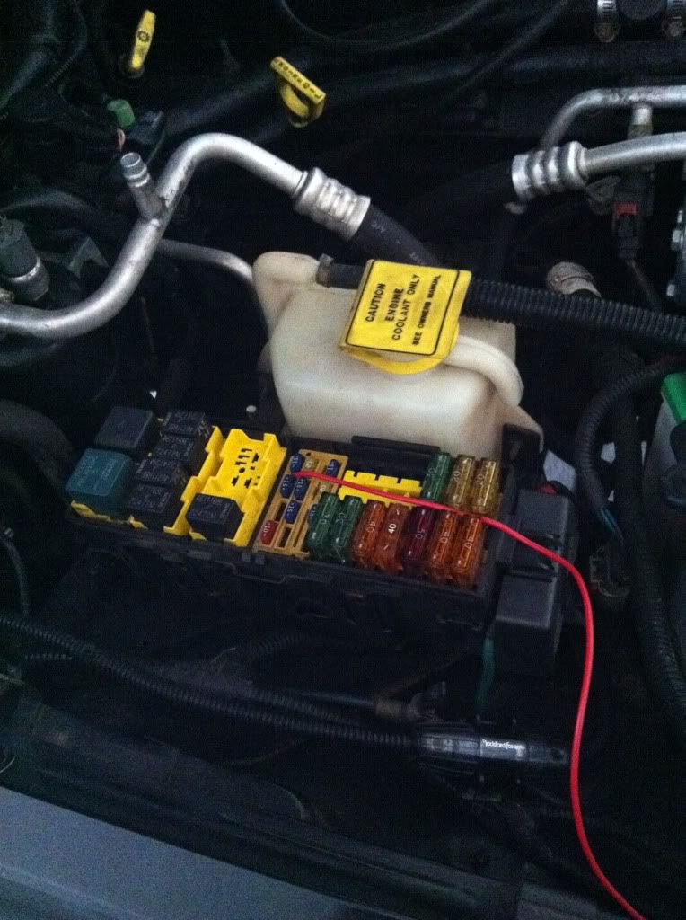
Repeat attaching and testing the turn signals for the other sides, and then snake the main power cord for the DRL. Connect both the DRLs to the main power cable you created in Step 9. Use a wire end loop connector to attach the (-) wire to the (-) side of the battery post. Strip the end of the (+) DRL main wire and pull the engine bay fuse shown in the below photo. Wrap several of the (+) wire strands around the post of the fuse then reseat the fuse in its spot. This is the only fuse for the 2000 Jeep that works. The other fuses if connected to the DRLs, will illuminate them 100% of the time, whether the car is running or parked. In other model Jeeps, you will need to test each fuse slot until you find one that only works when the engine is on.
Now secure any loose cables underneath the hood once you have put the DRLs in place and secured them as well. Make sure the load balancer is off on its own or attached to part of the frame as these things get HOT.
What you will need:
10mm LED bulbs 12V ready (pre-soldered to resistors preferred)
10mm LED bulb housings
Amber LED strip 2x30cm w/black backing
16-18 gauge wire
Soldering iron
Shrink tubing
Black electrical tape
Liquid electrical tape (optional)
Silicone sealant
8”x10” Lexan sheet
Dremel
Clear front turn signals
LED load balancers
6V battery (optional, used for testing)
2x Quick release connectors
6x T-Tap connectors
Wire loom conduit
Spray primer & black paint
Power drill and �” bit
Thin automotive strength 3M tape from Autozone
Core essentials:
10mm LED bulbs: These can be found in several places, but I found mine on eBay. The ones that I am using have a 140Kmcd candle rating. I own some 280Kmcd bulbs that I purchased a few years ago but did not use, only because I don’t know how to compute the proper resistor needed. The ones I purchased for this project came with resistors already attached. To take the guessing out, I recommend you do the same.
10mm LED bulb holders: I purchased mine 3 years ago when I originally purchased the bulbs I ended up not using. However, I found a website that sells the LED bulb holders, as well as the pre-wired bulbs. I believe this is the same vendor on eBay as well.
http://www.ledssuperbright.com/10mm-led-c-9
Clear turn signals:
These can be found on eBay and will range from $27 to as much as $40. Sometimes they have them, sometimes they don’t.
2x Amber 30cm LED strip:
These can also be found on eBay and are not required, but highly recommended.. especially if you want a front facing turn signal. Kind of important.
Step 1:(Prepping the clear lens)
Place clear turn signals in the oven on a wooden block at 300 degrees for about 10-12 minutes (or use a heat gun if you have one, I don’t). This process will soften up the adhesive holding the plastic lens to the bulb retaining housing. Remove the block of wood carefully with pot holders or heat gloves and place on kitchen counter. It is not hot enough to cause any burn damage. Pluck out the lens. I used the handle of a standard screwdriver which fit perfectly in the bulb opening. Next, create a �” inch border around the housing with a black permanent marker. The black line will be the area you will cut away during Step 2. When you finish, your clear housings should look like this.
Step 2: (Making the cut)
Grab the bulb housings and leave the clear front alone for now. Head to your garage, basement or wherever you do the most damage during projects. Grab the dremel, the appropriate cutting attachment, your goggles, and I recommend some gloves. Carefully cut at the black line until you end up with two pieces. Make sure you have a tight grip while cutting in case of dremel slippage. At this point, you may discard the bulb backings or save them for a future project. I saved mine for phase 2 of my project. When you finish, each of your signal housings should look like this:
Step 3: (The Lexan) “the lexan sheet was purchased from Home Depot for around $1.50”
Place your cut housing fronts on the lexan sheet and do a rough trace. This does not have to be exact because later, once they are attached, you can dremel away the extra lexan. Line up your 10mm bulb holders and try to evenly space them as best as you can. Do NOT remove the lexan protective sheet because you can use this to draw the frame on and make corrections before you start drilling holes. I recommend drawing a straight line across, then drawing around the bulbs so they are on an even plane. I used six bulbs in each side but it’s up to you how many you want to use. Place the clear cover on top to see how your final project should somewhat look like.
This next part and how you choose to do it is up to you. You can either drill the holes using the �” drill bit now, and then cut out the frame, or you can cut the frame out first, and drill the holes second. I cut the holes first. You may have to slightly enlarge the holes you cut. I used a dremel attachment to adjust the hole size. Remember, you can’t make a hole smaller, only larger so be careful. It does not have to be a snug fit, but you do want your LED bulb holders to cover the hole without having any visible gaps glaring through. Whichever route you take, try not to waste your lexan sheet. You will need to make two housings (one for each side) and you might mess up and need extra lexan to start one side over again. I messed up once, but still ended up having half the lexan sheet left over.
Step 4: (slowly coming together)
Once you have the bulbs where you want them, remove the bulbs and the bulb holders. I apologize for this next part because I did not take a photo, although it’s kind of important if you are using the amber LED strips. Before you start to permanently attach anything, you will need to cut a slit for the amber LED strip on each side of the DRL housing.
Using the silicone sealant (home depot, couple bucks), attach lexan lens to main DRL housing as shown below. Do not cover up the small hole you just made for the amber LED strip. The silicone I used dried pretty fast, but just to be safe, I did let them sit overnight.
Once the sealant has cured on both of the DRL housings, go back to the garage, basement or wherever and use the dremel to trim down the edges. This is more for visual appeal, but you don’t want the edges extending beyond the edges of the chrome housing.
Step 5 (color me bad)
Now that both your DRL holders are trimmed down and securely fastened, grab the gray primer and spray away. Once they have been primed, you can paint them any color you want. Painting them body color would be kind of cool. The type of paint you use will determine the drying time.
Once your housings have dried, attach the 10mm LED holders but DO NOT attach the 10mm LEDs yet. Next, remove the adhesive backing on your amber LED strips and grab the automotive strength 3M tape and cut a thin strip to reinforce the weak adhesive that your amber LED strips probably came with. You do not want these coming loose once you have sealed the main DRL housing. Slide your amber LEDs through the small opening you cut for each DRL housing. Make sure you press them down firmly so they stay attached and make sure you test them before committing to sealing them.
Note on amber LED strips. You can choose whichever kind looks best to you. I chose the kind that are pretty flexible, but hardly visible when turned off. The kind I chose comes with either a white backing or a black backing. I originally purchased the white, but thought it looked like crap, and purchased black instead, as it looks better with the black housing of the DRL. But to each his own. Below is an example of the white on black, and black on black.
White background LEDs Black background LEDsNow that the amber LED strips and the 10mm LED bulb holders are in place, use some adhesive on the lens and reattach. I put the lens and the DRL housings back in the oven for 300 degrees to soften up the OEM adhesive. Now that I have finished, I would not recommend doing this unless you reinforce it once it is dried with additional adhesive. Once you pull the bread out of the oven, reattach them then clamp, clamp, and clamp them together for a few hours. The longer, the better.
Step 6: (almost finished)
At this point, your DRL lens should be sealed from the front, and your amber LEDs are sealed inside. Put a dap of silicone over the opening that the amber LEDs was inserted into to water seal that opening. Now you can attach your 10mm LEDs. I used two small drops of hot glue on the back of each bulb to hold them into place. Then I used the silicone sealant to seal each bulb into place.
Step 7: (wiring part 1)
Each of these bulbs have a 12v resistor so we can wire them together in a parallel circuit without worrying about overload or frying of any components. This also ensures each bulb illuminates at its maximum instead of sharing the electric current. Group all the (+) wires together and all the (-) wires together for each side. Use the 6V battery (or another power source) to ensure all bulbs illuminate before soldering or shrink sealing wires together. If you use tape, you can always go back and make adjustments. Kill the lights to see what they are really going to look like. Don’t look directly into them or you will blind yourself.
Step 8 (wiring part 2)
Once you are comfortable with all bulbs working as desired, attach the (+) and the (-) wire clusters to a long (+) and (-) wire. The long wires will be used to run around the engine bay and connect to the power source. The best approach is to create a “T” connection between the long wire, and the 10mm LED wires. Because of the location of the battery on the 2000 Cherokee Sport, the passenger side DRL wiring will need to be much shorter than the driver side so plan accordingly. Finally, give all the wires a solid sealing. They will be somewhat exposed when finished so seal, seal, and seal. But don’t seal too much, because you may need to replace an LED, but hopefully not for a long time. Test the lights again before adding any of the connectors. I picked up the connectors at Home Depot for around $5. You will only need two pair.
Preparing to run the DRLs with the ignition is easy to do. Preparing to run the amber LEDs with the turn signals however is somewhat daunting. You will need to use some extra pieces of the 16-18 gauge wire and build some wire extensions for the amber LED wiring. The amber LEDs come with some really crappy and weak wiring. Use the T-Tap connector’s male ends and attach to the amber LED wires.
Step 9 (wiring part 3)
At this point, both the DRL units should have male T-Tap connectors for the amber LEDs and the both DRL units should also have one of the other connectors you purchased. You should use the shrink tubing on these connections. Take the plastic wire loom and wrap the long wires so it looks nice and neat. Tape the ends to ensure the loom does not slide around.
We are almost finished, but now we need to make the power source wiring. You will need to create a positive and a negative wire connection. The length is up to you, but I went with about 18” inches for each. This part will sound tricky. One end power wire connection will only have ONE positive and ONE negative wire. This will be used for the main power and ground of the DRLs.
The OTHER side will need TWO (+) and TWO (-) wires. This can be accomplished using the “T” connection technique as touched on earlier. Okay, here’s how to do it. Take an 8” inch positive wire, strip both ends, then cut around the center with a blade but do not cut the wire. Pull the center apart at the cut until you have about �” or less of exposed wire. Take the 18” inch positive wire and strip about 2” off the end. Take the stripped end and wrap it around the exposed center of the 8” inch wire, then twist the 2” exposed wire around itself. When finished, it should look like a “T” or a “Y” I suppose. Wrap the connected wires with whatever you choose, and do the same for the (-) wire. In the end, you will have your two positive and negative wires on one end, and one (+) and (-) on the other.
Now attach the OPPOSITE connector from what you used for the DRL units to each pair of positive and negatives. You are NOT putting the two reds and two blacks together. ONE (+) and ONE (-) per connector. You will now have somewhere to plug BOTH the DRL units into. Finish by wrapping the power source wiring with the conduit loom but be sure to leave a foot or so unwrapped so that you can extend the positive wire one way, and the negative wire to the battery.
Step 10: (putting it all together)
Lay out what you have on the floor. You should have one DRL unit with longer wiring than the other. You should also have your power connection cord created in the last step (not shown in my photo). Also notice I have the big connectors on both my amber LEDs. I know I said to use the T-Tap connectors but just trust me.
***You should now add the load balancers. I would recommend using T-Tap connectors here as well. These will need to be attached to the amber DRL extension (+) and (-) wires created in Step 8. Without a load balancer, you will get the fast blink / bulb out warning when you use the amber LEDs. LEDs do not demand enough power so the ECU thinks there is a bulb out.
Head out to the Jeep and remove your OEM turn signals (remove headlamp frame first 2 screws, then turn signals…. 2 screws). Pull back one of the 3157 bulb wiring. You want to tap into the ground (black or brown) and the solid green wire (I think). Never rely solely on the splicing connectors so take your box knife and carefully cut a half circular incision around the OEM wire. Bend the wire back and forth a few times to expose the wire under the cut. Take the female end of the T-Tap connector and clamp it over the exposed wire. Now set your DRL unit on the engine bay around and plug in the amber LEDs to OEM wiring. Turn on the vehicle to test using the hazards. Check the regular blinker as well. If it fast blinks, make sure you remembered to attach the load balancers. If you remove the actual 3157 bulb, then it will blink faster than normal, but not rapidly fast. Once you are all set with the amber LEDs, run the long power wires from your DRL unit through the opening under the headlamp and snake around near the battery area. My driver side cord is long enough to skirt near the engine bay body all around.
The million dollar question: What do I do with the OEM 3157’s? There are two on each side, at least with the 2000 Jeep. Well… I will be using one on each side for a future project. The one I tapped into can have the bulb removed, then the housing tucked down somewhere you make room. I purchased bulb covers for mine in the meantime then wrapped the bulb covers in black duct tape so the light won’t bleed through and I won’t get a bulb out warning.
Step 11 (All systems Go)
Repeat attaching and testing the turn signals for the other sides, and then snake the main power cord for the DRL. Connect both the DRLs to the main power cable you created in Step 9. Use a wire end loop connector to attach the (-) wire to the (-) side of the battery post. Strip the end of the (+) DRL main wire and pull the engine bay fuse shown in the below photo. Wrap several of the (+) wire strands around the post of the fuse then reseat the fuse in its spot. This is the only fuse for the 2000 Jeep that works. The other fuses if connected to the DRLs, will illuminate them 100% of the time, whether the car is running or parked. In other model Jeeps, you will need to test each fuse slot until you find one that only works when the engine is on.
Now secure any loose cables underneath the hood once you have put the DRLs in place and secured them as well. Make sure the load balancer is off on its own or attached to part of the frame as these things get HOT.


Thread
Thread Starter
Forum
Replies
Last Post
Currently Active Users Viewing This Thread: 1 (0 members and 1 guests)