Testing coil rail??

 01-12-2015, 07:53 AM
#2
CF Veteran

Join Date: Nov 2010
Location: In the middle of Minnesota!
Posts: 5,805
Received 99 Likes
on
88 Posts
Year: 1999
Model: Cherokee
Engine: 4.0
This isn't 100% conclusive, but it's the only technique I'm aware of.
--------------------------------------------------------------------------------------
The coil design for the 00-01 is significantly different than that of the single coil and distributor setup on the earlier 4.0. You basically have three coils firing 6 plugs in the correct sequence, every crankshaft rotation (waste spark design). This is an engineering departure from the older, single spark every other crankshaft rotation.
You can test the coil pack like you would the old single coil design, but its more technically involved than physically accessing the spark plug end. Because of the design of the coil rail, don’t test the coil rail one spark plug port at a time. Testing one port at a time causes the remaining coil ports to be free floating (ie, not properly grounded through the spark plug). Free floating an encapsulated coil secondary causes significant increases in the voltage induced in the secondary. This increased voltage can easily exceed the dielectric breakdown of the coil secondary and could cause the coil windings to arc internally and break down the insulation. If this happens, it has the effect of reducing coil energy delivery potential in the best cases and in the worst cases, causes the coil to fail. You need to install all 6 spark plugs to ensure you won’t damage the coil rail.
Because it is difficult to guarantee that you can correctly ground all 6 plugs at once, you should make up 6 separate jumper wires about 2 feet long. Pull the rail and flip it upside down. Insert 6 sparkplugs into the rail. Attach one end of a jumper wire to the threaded part of the sparkplug with a large mouth alligator clip and attach the other end of the jumper wire to engine ground.
Once all 6 are hooked up this way, you can then perform your engine cranking test while observing spark on all 6 plugs. You are looking for a strong, BLUE, snapping spark. Yellow/orange/white indicates a weak spark.
The following users liked this post:
99WJohnyKhaos (07-27-2020)
01-12-2015, 09:50 AM
#4
CF Veteran
Join Date: Aug 2010
Location: Canton, MI
Posts: 8,357
Likes: 0
Received 82 Likes
on
67 Posts
Year: 1999
Model: Cherokee
Engine: 4.0
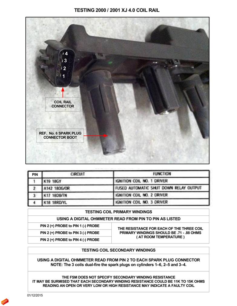
See if you can perform the tests shown below and give me some feedback.
I don't have a coil rail that I can perform these tests on - specically the secondary coil windings tests. I would appreciate you trying these tests and if any changes need to be made I will do so.
Edit: Testing of the secondary windings requires removal of the coil rail.
Thanks
I don't have a coil rail that I can perform these tests on - specically the secondary coil windings tests. I would appreciate you trying these tests and if any changes need to be made I will do so.
Edit: Testing of the secondary windings requires removal of the coil rail.
Thanks
Last edited by CCKen; 01-12-2015 at 10:03 AM.
01-12-2015, 06:40 PM
#6
Junior Member
Thread Starter
Join Date: Dec 2014
Location: McHenry,IL
Posts: 57
Likes: 0
Received 0 Likes
on
0 Posts
Year: 2000
Model: Cherokee
Engine: '91 4.0 H.O
Ok ccken I gave your test ago. Primary windings came up to .7 - 1 ohm. Secondary I couldnt get any readings, was always OFL.
Trending Topics
01-13-2015, 07:54 AM
#8
Junior Member
Thread Starter
Join Date: Dec 2014
Location: McHenry,IL
Posts: 57
Likes: 0
Received 0 Likes
on
0 Posts
Year: 2000
Model: Cherokee
Engine: '91 4.0 H.O
OFL means overflow so like an open circuit. I have my multimeter on auto, but I will try it ago today to see if I can get anything off it.
01-13-2015, 09:02 AM
#9
CF Veteran
Join Date: Aug 2010
Location: Canton, MI
Posts: 8,357
Likes: 0
Received 82 Likes
on
67 Posts
Year: 1999
Model: Cherokee
Engine: 4.0
Here's a (edited) procedure from eHow on how to check the coil rail on a GC. This doesn't make sense to me at all. I'm going to check on the Allpar Jeep forum to see if anyone there has a good procedure.
eHow:
Turn on your ohmmeter and set it to the 20,000 ohms range.
Touch the ohmmeter leads to the connectors in the first spark plug boot. Your meter should read from 6,000 to 30,000 ohms. Repeat this on each spark plug boots. Replace the coil pack if the measurement falls outside of this range.
Set the ohmmeter to the 10 ohms range. Touch the center prong on the electrical connector with one of the leads and the first spark plug boot with the other. Your meter should read less than 2 ohms. Repeat this while touching the second lead to each spark plug boot. Replace the coil pack if the measurement is higher than 2 ohms.
01-22-2015, 05:49 PM
#10
CF Veteran
Join Date: Aug 2010
Location: Canton, MI
Posts: 8,357
Likes: 0
Received 82 Likes
on
67 Posts
Year: 1999
Model: Cherokee
Engine: 4.0
Learned something today concerning the 2000/2001 coil rails.
I hope this clarifies not being able to read resistnce of the coil secondary windings.
tjwalker has the only way to actually check the secondaries. A chap on the Allpar forum said about the same things as TJ.
His last sentence in this email sums it up .
A response from Wells Vehicle Electronics to my inquiry about what are the internal workings of the Wells C1263 Coil that I cannot read the resistance of secondary circuits:
Ken,
In the way that coils work, magnetic fields move when the current to the primary is turned either on or turned off. To start, the current in the primary coil is zero. We turn on the power driver and then, against the opposition of the coils resistance AND inductance, the current builds to some value set by the manufacturer. For discussion, 6.5 amps is about right. When the current has built up to that level (between 1 and 3 milliseconds depending on the coil) we are ready to turn it off, collapse the magnetic field and produce the spark.
To a much lesser extent, this also happens when you first turn the coil on. The change from zero current to a positive value will produce a small output voltage from the coil. This is a positive value of voltage, usually in the range of 1500-2000 volts. This should not be enough to fire the spark plug. If it did, you would get a wildly out of time combustion event.
Many of the Japanese coil makers feel that with their coil designs this could be a problem. They call it feed forward voltage. They say that depending on the design of the coil the number could be as high as 2500 volts and under some circumstances this might produce a weak, unwanted spark that is greatly advanced from where it should be.
What is also different about this potential is that it is a positive voltage where the output for normal use from a coil is negative.
The solution is to put a high voltage diode inside the coil. It is located between the output of the coil itself and the terminal that is the output of the coil assembly. This blocks any positive going voltage and prevents the possibility of an unwanted spark/combustion event.
The answer to your question is that your ohmmeter is blocked from reading the resistance of the coil by the presence of this diode.
Mike Dale
Sr. Coil Design Engineer
Wells Vehicle Electronics.
January 22, 2015
 01-23-2015, 09:12 AM
#12
Senior Member

Join Date: Apr 2012
Location: Ocean, New Jersey
Posts: 578
Likes: 0
Received 4 Likes
on
4 Posts
Year: 2000
Model: Cherokee
Engine: 4.0
Learned something today concerning the 2000/2001 coil rails.
I hope this clarifies not being able to read resistnce of the coil secondary windings.
tjwalker has the only way to actually check the secondaries. A chap on the Allpar forum said about the same things as TJ.
His last sentence in this email sums it up .
A response from Wells Vehicle Electronics to my inquiry about what are the internal workings of the Wells C1263 Coil that I cannot read the resistance of secondary circuits:
Ken,
In the way that coils work, magnetic fields move when the current to the primary is turned either on or turned off. To start, the current in the primary coil is zero. We turn on the power driver and then, against the opposition of the coils resistance AND inductance, the current builds to some value set by the manufacturer. For discussion, 6.5 amps is about right. When the current has built up to that level (between 1 and 3 milliseconds depending on the coil) we are ready to turn it off, collapse the magnetic field and produce the spark.
To a much lesser extent, this also happens when you first turn the coil on. The change from zero current to a positive value will produce a small output voltage from the coil. This is a positive value of voltage, usually in the range of 1500-2000 volts. This should not be enough to fire the spark plug. If it did, you would get a wildly out of time combustion event.
Many of the Japanese coil makers feel that with their coil designs this could be a problem. They call it feed forward voltage. They say that depending on the design of the coil the number could be as high as 2500 volts and under some circumstances this might produce a weak, unwanted spark that is greatly advanced from where it should be.
What is also different about this potential is that it is a positive voltage where the output for normal use from a coil is negative.
The solution is to put a high voltage diode inside the coil. It is located between the output of the coil itself and the terminal that is the output of the coil assembly. This blocks any positive going voltage and prevents the possibility of an unwanted spark/combustion event.
The answer to your question is that your ohmmeter is blocked from reading the resistance of the coil by the presence of this diode.
Mike Dale
Sr. Coil Design Engineer
Wells Vehicle Electronics.
January 22, 2015
I hope this clarifies not being able to read resistnce of the coil secondary windings.
tjwalker has the only way to actually check the secondaries. A chap on the Allpar forum said about the same things as TJ.
His last sentence in this email sums it up .
A response from Wells Vehicle Electronics to my inquiry about what are the internal workings of the Wells C1263 Coil that I cannot read the resistance of secondary circuits:
Ken,
In the way that coils work, magnetic fields move when the current to the primary is turned either on or turned off. To start, the current in the primary coil is zero. We turn on the power driver and then, against the opposition of the coils resistance AND inductance, the current builds to some value set by the manufacturer. For discussion, 6.5 amps is about right. When the current has built up to that level (between 1 and 3 milliseconds depending on the coil) we are ready to turn it off, collapse the magnetic field and produce the spark.
To a much lesser extent, this also happens when you first turn the coil on. The change from zero current to a positive value will produce a small output voltage from the coil. This is a positive value of voltage, usually in the range of 1500-2000 volts. This should not be enough to fire the spark plug. If it did, you would get a wildly out of time combustion event.
Many of the Japanese coil makers feel that with their coil designs this could be a problem. They call it feed forward voltage. They say that depending on the design of the coil the number could be as high as 2500 volts and under some circumstances this might produce a weak, unwanted spark that is greatly advanced from where it should be.
What is also different about this potential is that it is a positive voltage where the output for normal use from a coil is negative.
The solution is to put a high voltage diode inside the coil. It is located between the output of the coil itself and the terminal that is the output of the coil assembly. This blocks any positive going voltage and prevents the possibility of an unwanted spark/combustion event.
The answer to your question is that your ohmmeter is blocked from reading the resistance of the coil by the presence of this diode.
Mike Dale
Sr. Coil Design Engineer
Wells Vehicle Electronics.
January 22, 2015
Thank you so much for sharing this information. This is very helpful a could potentially save a lot of folks including me the $100 cost of an unnecessary ignition coil rail replacement.
01-23-2015, 10:08 AM
#15
Senior Member

Join Date: Sep 2014
Location: Saginaw Mi area
Posts: 580
Likes: 0
Received 0 Likes
on
0 Posts
Year: 1994
Model: Cherokee
Engine: 4.0
So, that diode is the item that tricked us all !! And reading that clarifies why they used the diode. Great information
But: on the other hand I would think a reading could be had when the ohmeter leads were reversed, since the diode lets current flow in one direction & no the other. Weird....too much to think about !
But: on the other hand I would think a reading could be had when the ohmeter leads were reversed, since the diode lets current flow in one direction & no the other. Weird....too much to think about !
Last edited by steelybill; 01-23-2015 at 10:12 AM.