Jeep Grand Cherokee 1993-1998: How to Test and Replace Throttle Position Sensor
The Throttle Position Sensor (TPS) sends the throttle plate position to the ECU. A faulty TPS can cause ignition and idling issues, so read on to learn how to test and replace yours for a fraction of the cost of having it done professionally.
This article applies to the Jeep Grand Cherokee ZJ (1993-1998).
The Throttle Position Sensor (TPS) sits on the throttle body, and sends a voltage reading to the ECU that represents the position of the throttle plate. The ECU uses this reading to adjust ignition settings, regulate fuel injectors, and other settings to keep your engine running smoothly. A faulty TPS can cause a number of engine performance issues, so learn how to test it and replace it with a minimal time investment as well as just a few basic tools.

Materials Needed
- Multimeter
- T20 Torx screwdriver
- Throttle Position Sensor replacement
- Paperclip or very thin metal object
- Alligator clips
Step 1 – Locate the TPS
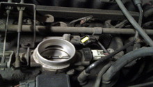
Refer to Figure 1 and note the location of the sensor in the throttle body by the intake.

Step 2 – Identify the three connector wires
The TPS functions by sending a voltage signal to the ECU, which represents the position of the throttle. The connection to the ECU has three wires:
- Ground
- 5V voltage supply
- Signal return wire
You will need to do a little investigative work to determine which wire carries the signal needed to test the sensor. Start by putting the ignition in the "on" position.
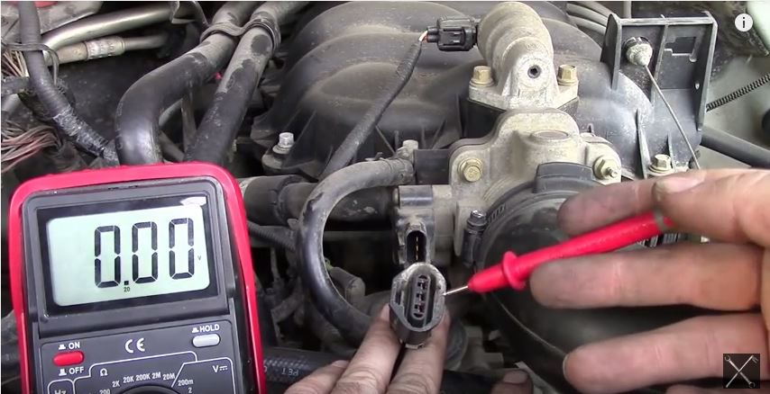
Next, remove the connector from the TPS and set your voltmeter to 20V DC. Connect the black probe to your battery ground and then test each of the three connector leads to determine which carries the 5V supply from the ECU. Note the pin and wire color for this 5V supply. Use Figure 2 as a reference.
To find the ground wire, set your multimeter to Ohms and use the audio feature to probe the remaining two wires. Be very careful not to probe the 5V wire during this test. Once you hear the beep, you have identified the ground wire. Now you know which of the wires carries the correct signal for testing.
Step 3 – Test the TPS by manipulating the throttle
Using a multimeter, you can test the function of the TPS by probing the signal wire and manually manipulating the throttle. The signal wire should send around one volt with the throttle closed, and close to five when it's fully open.
Plug the connector back into the TPS, then back-probe the ground and signal wires for easier voltage reading. To back-probe the connector, you insert a very thin metal object (like a paperclip) into the back of the connector, being sure to contact the metal further down in the wire channel. It is important when doing this to not cross your back-probes—bend them away from each other to avoid this problem.
Use alligator clips, as shown in Figure 3, to free up your hands for adjusting the throttle. Connect one clip to the ground and the other to the signal wire. With your multimeter set to 20V DC, you should be getting just below one volt as an idle reading with the throttle closed, as shown in Figure 4.
By manually opening the throttle plate slowly, you should see the voltage steadily climb from below one volt to approximately 4.6 volts as shown in Figure 5. Slowly releasing it back to the closed position should likewise decrease the voltage steadily back down to below 1V.
Any jumps in the voltage reading up or down could signal a faulty TPS. Another good test is to tap on the sensor while opening and closing the throttle to simulate its function while the engine is running. The problem may not reveal itself with the engine off, so it's best to simulate it as closely as possible during your testing.
Is the sensor bad? No problem, let's replace it in the next step.

Figure 3. Back-probing the connector. 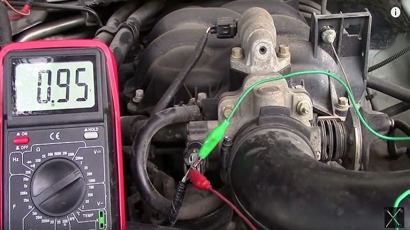
Figure 4. Base voltage (throttle closed). 
Figure 5. High voltage (throttle open).
Featured Video: How to Test TPS
Step 4 – Remove and replace the defective sensor
Turn off the ignition and unplug the wire connector. Remove the two screws using a T20 Torx screwdriver, and gently remove the defective unit.
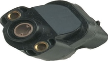
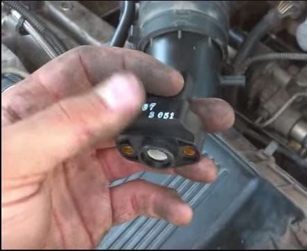
Replace it with a new unit (shown in Figure 6). Gently insert it so as not to disrupt the position of the throttle plate. Fasten the two screws, plug in the connector and you are good to go!
Featured Video: TPS Installation
Related Discussions
- High Idle When Cold Started - CherokeeForum.com
- Renix Tips - CherokeeForum.com
- Bad TPS Symptoms - CherokeeForum.com
- TPS Keeps Going Bad - CherokeeForum.com