When you click on links to various merchants on this site and make a purchase, this can result in this site earning a commission. Affiliate programs and affiliations include, but are not limited to, the eBay Partner Network.
So I have been having an issue with Beast, ignition switch will not release from starter circuit, so I have to pull it back manually. However, if the issue was that simple, this wouldn't be a post! Since it started doing that, it will not return to a normal run circuit. My accessories (radio, 12V output (cigarette lighter)) will not come on all the time, and sometimes my blinkers don't work. I didn't know about that last bit until I was pulled over recently! So I am jumping into an already planned upgrade, a pushbutton ignition!
I have found an excellent YouTube video to follow, but I am having an issue figuring out jeep specific stuff. The following is what I found on my column, down from the ignition switch:
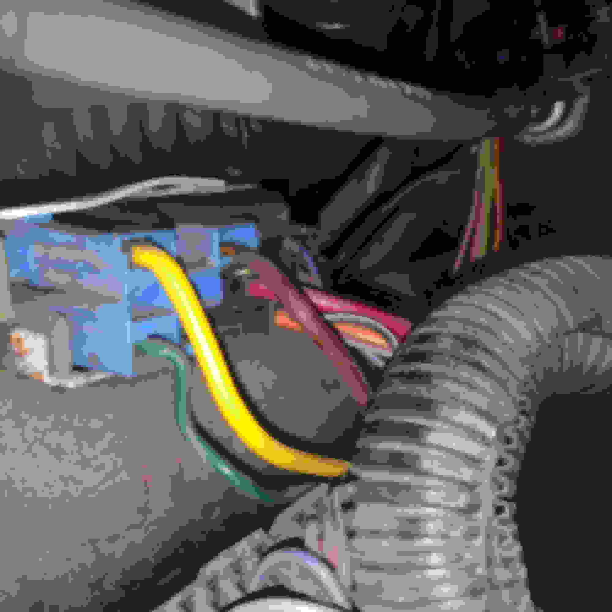
The problem I have is those unknown wires, and not knowing what the accessory circuit is. I will be crawling around with a multimeter soon, but wanted to "cheat" and ask you guys for info. Also wanted to share this upgrade with you all! As a bonus, here is a pic of my ignition wiring as it sits:
Thanks David, and no worries chevmac. As mentioned, I had already planned on doing this. I already have the switch, I am looking for info on these unknown wired before cutting them all and running wires to the new switch. My plan is to leave the key barrel intact so I still have steering wheel lock functionality. Anyone have insight to these unknown wires? Testing will commence today.
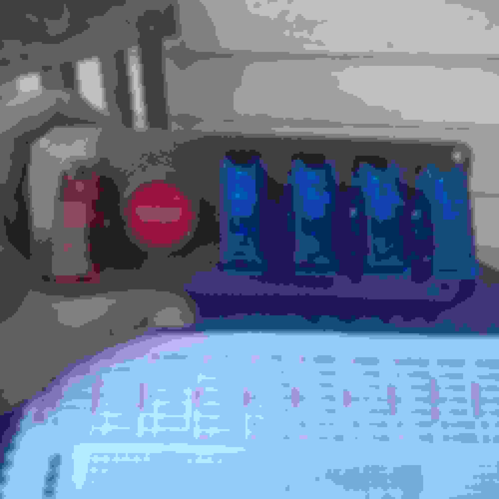
Well turns out I was looking at the wrong connector. What a headache! For a 1990 Jeep Cherokee Pioneer, the ignition switch is located on top of the steering column way down past the instrument cluster. Here are some pics of my switch:
From steering column, note the plastic sheathing. That's the RENIX ECU harness.
Close up of blue side of connector
I am having difficulties getting the black side to load. Anyway, here's my wiring put to paper:
The essence of it is:
Yellow: ignition
Green: Starter Relay
Brown: Accessories
Red: hot from Battery (fused link)
Orange: Distributer
Black/White: Brake warning switch
Gray/Red: Park brake warning switch
Violet: Instrument cluster
I will submit the wiring diagram later, and Sunday I should be posting install pics!
Even with steering wheel lock? Where I live, I leave my keys in the Jeep, and it's a manual, and currently with my dash ripped out there is very low appeal to take, well, anything.
Not sure the pic advises your statement. Is that
a. a theft gone wrong
b. poor electrical work?
If it's a, I am fortunate enough to drive a vehicle that is 78% theft-proof, as it is a manual (reported two years ago, only 18% of Americans can drive stick). Secondly, given the current state of rebuild, I don't foresee many people taking any interest in theft.
If b, I work with electricity every day, especially building of circuits. While that doesn't mean I know everything, I know enough to not get myself hurt, or damage the Jeep.
My question, if you go back to the original post, was to find a way to get going faster, but I seem to have worked it out on my own. Mostly, anyways. However, a battery kill switch is not a bad idea, perhaps that will be my next electrical add-on!
However, a battery kill switch is not a bad idea, perhaps that will be my next electrical add-on!
It doesn't make the ECM super happy to have it reset every time. I think if you power the B+ Latch relay separate from whatever battery isolation/kill switch you have it will work better, but I haven't tried this.
Most guys just do a fuel pump cut off switch because it's a lot easier, assuming theft deterrent is the point.
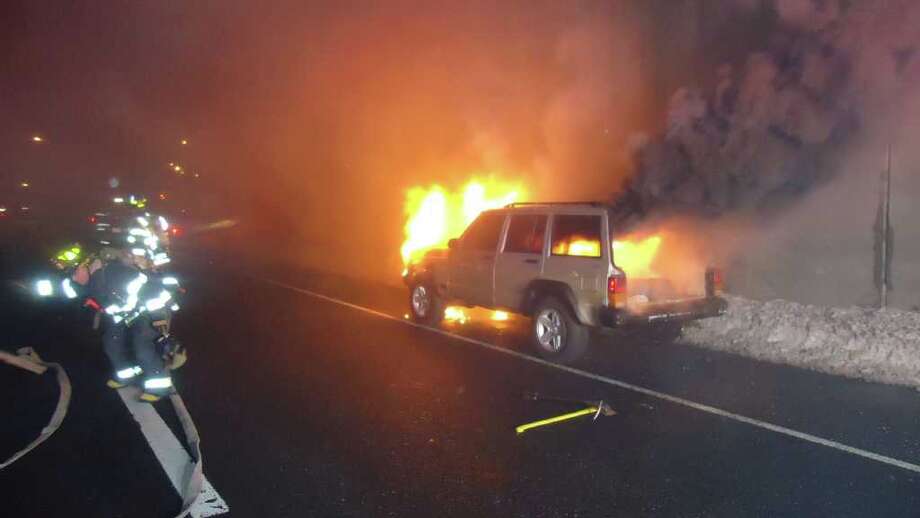
Proper electrical connections offer low resistance like this:
The image you posted is an example of a fire hazard.
Corrosion + electricity = high resistance which causes heat.
That heat could cause you to hear fire trucks very close by @ 3:00am.
Ahh, thanks for clarifying! That's a very good observation, and yet another reason to get rid of the stock wiring. I would like to note that it does not have high enough resistance to cause a fire, it's dusty but not overly corroded. Nice pic of what looks to be a brand new switch!
2drx4, good point, thinking about it going remote power with ecu constant power is overly complicated. Will check out an easy kill switch for fuel pump.
pump.Thanks for the input, I will post my updated wiring schematic tomorrow. Switch will go in next weekend, full video link as well.
4 switch Pushbutton wiring diagram
Here is the diagram. Sorry it took so long!
Power to the switches is carried from the first switch to a common low amp bus bar. See the "pink" circuit. That is going to receive power from the clock wires (hence pink, as that's the stock color) since the clock is a constant +12V source. The bus bar provides power to Pin85 of the relay, Pin86 is the ground. When switch1 is energized, it will provide power to the relay, causing Pin30 (STOCK red ignition wire to the ignition) and Pin87 (blue) contacts to close, completing the circuit and providing power to the ignition bus bar (in blue). When that bus bar is energized, it will provide power to STOCK orange and STOCK yellow ignition wires. and provide potential to Pin1 of the push button switch. When depressing the switch, it will close contact to Pin2 of the push button switch, providing the current to STOCK green wire, which energizes starter.
Meanwhile, the pink, low amp bus bar feeds the positive side of the remaining switches, of which only one will be used for the moment. The black bus bar is for the ground. Accessory switch (the first beyond the starter button) labeled ACC1, will energize the final stock ignition wire, STOCK brown, which is the accessory circuit for the Jeep.
I have not provided for the black/red and gray/white wires, but the could easily be put on to a bus bar off the ACC1 switch, but for the moment, I don't even have that module. Read up for what they do.
Why bus bars? It's cleaner than a splice, and easier to manage. Also, I can add to any of it at any time. ACC2-4 will he used eventually for, say, electric fans, replacing the headlight switch, fog lights, etc. They are undecided at the moment. Please let me know what you think!
I almost forgot, the third pin on each of the DTSP switches is for an LED light. If you don't have lit switches, you do not need to provide a ground to any switch. Indeed, the isn't a way to ground the switches. When you close the circuit, it energizes the LED bulb since it's grounded.
Please be gentle of my drawing capabilities, I'm no artist, and normally would have used a ruler to at least clean it up a bit.
 07-25-2018, 11:16 PM