New LED Rocker switch help!
 02-18-2015, 07:42 PM
#1
Member
Thread Starter
Join Date: May 2011
Location: Olympia WA
Posts: 142
Likes: 0
Received 0 Likes
on
0 Posts
Year: 1994
Model: Cherokee
Engine: 4.0
So I am by no means an electrician so when it comes to wiring up lights i always have a hell of a time, so this time I decided to come here first! I am going to be adding a fair amount of new LED lights to my Cherokee. I'm using anywhere from 18watt LED to a 300watt LED Bar and several sizes in between mostly 27watt. I have 8 blue LED rocker/toggle switches that I want to use they are the 5 pin dual LED back light style. Here is my wiring diagram i put together can someone who knows what they are doing please take a look and see if there are any issues? Thanks
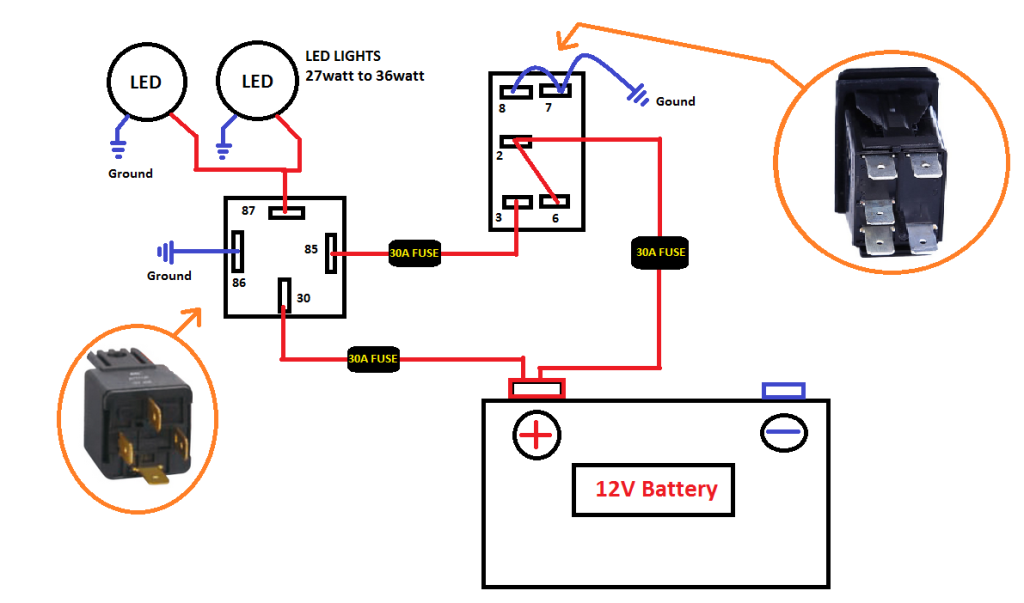
<a href="http://s1372.photobucket.com/user/millergt1551/media/LEDLIGHTS%20WIRE_zpsdk5nzuwm.png.html" target="_blank"><img src="http://i1372.photobucket.com/albums/ag349/millergt1551/LEDLIGHTS%20WIRE_zpsdk5nzuwm.png" border="0" alt=" photo LEDLIGHTS WIRE_zpsdk5nzuwm.png"/></a>
Also can I run them in a parallel or some kind of circuit to save excess wires?
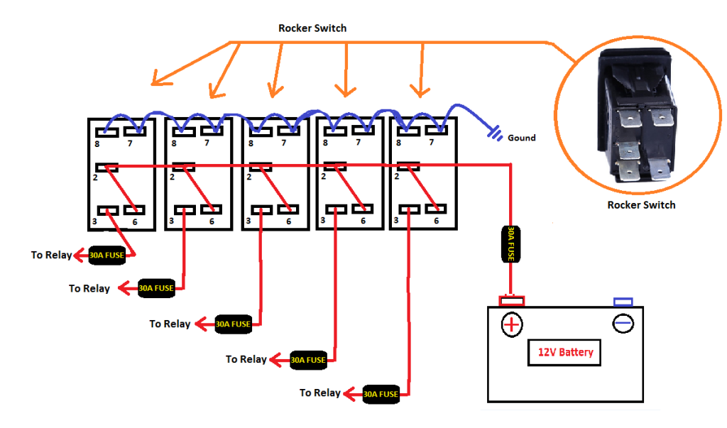
<a href="http://s1372.photobucket.com/user/millergt1551/media/LEDLIGHTS%20WIRE%20ROCKER_zpsdai81uae.png.html" target="_blank"><img src="http://i1372.photobucket.com/albums/ag349/millergt1551/LEDLIGHTS%20WIRE%20ROCKER_zpsdai81uae.png" border="0" alt=" photo LEDLIGHTS WIRE ROCKER_zpsdai81uae.png"/></a>
 02-18-2015, 08:56 PM
#2
Member
Thread Starter
Join Date: May 2011
Location: Olympia WA
Posts: 142
Likes: 0
Received 0 Likes
on
0 Posts
Year: 1994
Model: Cherokee
Engine: 4.0
also I want to set up my aux reverse lights to run off the OEM reverse lights and off a switch, anyone know how to do this?
02-19-2015, 07:58 AM
#3
CF Veteran
Your understanding of how a relay works is sound but I'd double-check the outputs of those switches. I could be mistaken, but if they're the Carling style you should only have one common ground. The other ground you have per switch is usually connected to a illuminated source so the switch lights up when you turn your lights on...
You might be a little over-fused too. In your diagram, the wire running from the battery to your switch and then to your relay can and should be relatively light-duty. It doesn't take much at all to throw those box relays- we're talking milliamps. A 30amp fuse is too much- the little 5amp fuses are more than enough and you won't risk damaging the relay or switch instead. Remember, you want the fuse to be lower capacity than your other components. A fuse next to the battery is enough too. No need for one between the switch and relay.
Running them in parallel is the way to go. One option for a reverse trigger is to put another relay inline and tapped into your reverse light +. The reverse light turning on throws the signal to the secondary relay. The primary relay only activates when you throw the switch. Keeps it legal that way. Only turns on IF the switch is on AND you're in reverse.
02-19-2015, 12:01 PM
#4
Member
Thread Starter
Join Date: May 2011
Location: Olympia WA
Posts: 142
Likes: 0
Received 0 Likes
on
0 Posts
Year: 1994
Model: Cherokee
Engine: 4.0
Your understanding of how a relay works is sound but I'd double-check the outputs of those switches. I could be mistaken, but if they're the Carling style you should only have one common ground. The other ground you have per switch is usually connected to a illuminated source so the switch lights up when you turn your lights on...
You might be a little over-fused too. In your diagram, the wire running from the battery to your switch and then to your relay can and should be relatively light-duty. It doesn't take much at all to throw those box relays- we're talking milliamps. A 30amp fuse is too much- the little 5amp fuses are more than enough and you won't risk damaging the relay or switch instead. Remember, you want the fuse to be lower capacity than your other components. A fuse next to the battery is enough too. No need for one between the switch and relay.
Running them in parallel is the way to go. One option for a reverse trigger is to put another relay inline and tapped into your reverse light +. The reverse light turning on throws the signal to the secondary relay. The primary relay only activates when you throw the switch. Keeps it legal that way. Only turns on IF the switch is on AND you're in reverse.
You might be a little over-fused too. In your diagram, the wire running from the battery to your switch and then to your relay can and should be relatively light-duty. It doesn't take much at all to throw those box relays- we're talking milliamps. A 30amp fuse is too much- the little 5amp fuses are more than enough and you won't risk damaging the relay or switch instead. Remember, you want the fuse to be lower capacity than your other components. A fuse next to the battery is enough too. No need for one between the switch and relay.
Running them in parallel is the way to go. One option for a reverse trigger is to put another relay inline and tapped into your reverse light +. The reverse light turning on throws the signal to the secondary relay. The primary relay only activates when you throw the switch. Keeps it legal that way. Only turns on IF the switch is on AND you're in reverse.
 02-20-2015, 09:55 AM
#6
CF Veteran
The fuse on the left, powering your lights, should still be a higher-rated fuse. What wattage lights are you installing?
Example: 200watts � 12v = 16amps. I'd put a 20amp fuse in that one.
Also keep in mind that you can use the ground to switch a relay- that way, worse case scenario (if a trigger wire shorted) the relay would just stay engaged or disengaged rather than blowing a fuse. See the model "Controlling a Relay" at the bottom of this page: http://www.bcae1.com/relays.htm
02-20-2015, 10:00 AM
#7
CF Veteran
One more thing we haven't mentioned yet- wire gauge. Make sure the wires you run can handle the amperage. See the table here:
http://www.engineeringtoolbox.com/am...uge-d_730.html
Hint: An Ethernet cable has 8 internal color-coded wires that are great as trigger wires for relays. Remember from an earlier post that relays need very little to switch. I've used this method to separate my fuse box and my switch box- running a single Ethernet wire through the firewall with the ability to control up to 8 accessories.
Trending Topics
02-20-2015, 11:21 AM
#8
Member
Thread Starter
Join Date: May 2011
Location: Olympia WA
Posts: 142
Likes: 0
Received 0 Likes
on
0 Posts
Year: 1994
Model: Cherokee
Engine: 4.0
One more thing we haven't mentioned yet- wire gauge. Make sure the wires you run can handle the amperage. See the table here: http://www.engineeringtoolbox.com/am...uge-d_730.html Hint: An Ethernet cable has 8 internal color-coded wires that are great as trigger wires for relays. Remember from an earlier post that relays need very little to switch. I've used this method to separate my fuse box and my switch box- running a single Ethernet wire through the firewall with the ability to control up to 8 accessories.
02-20-2015, 11:30 AM
#9
Member
Thread Starter
Join Date: May 2011
Location: Olympia WA
Posts: 142
Likes: 0
Received 0 Likes
on
0 Posts
Year: 1994
Model: Cherokee
Engine: 4.0
One more thing we haven't mentioned yet- wire gauge. Make sure the wires you run can handle the amperage. See the table here: http://www.engineeringtoolbox.com/am...uge-d_730.html Hint: An Ethernet cable has 8 internal color-coded wires that are great as trigger wires for relays. Remember from an earlier post that relays need very little to switch. I've used this method to separate my fuse box and my switch box- running a single Ethernet wire through the firewall with the ability to control up to 8 accessories.
02-23-2015, 02:49 PM
#12
Junior Member
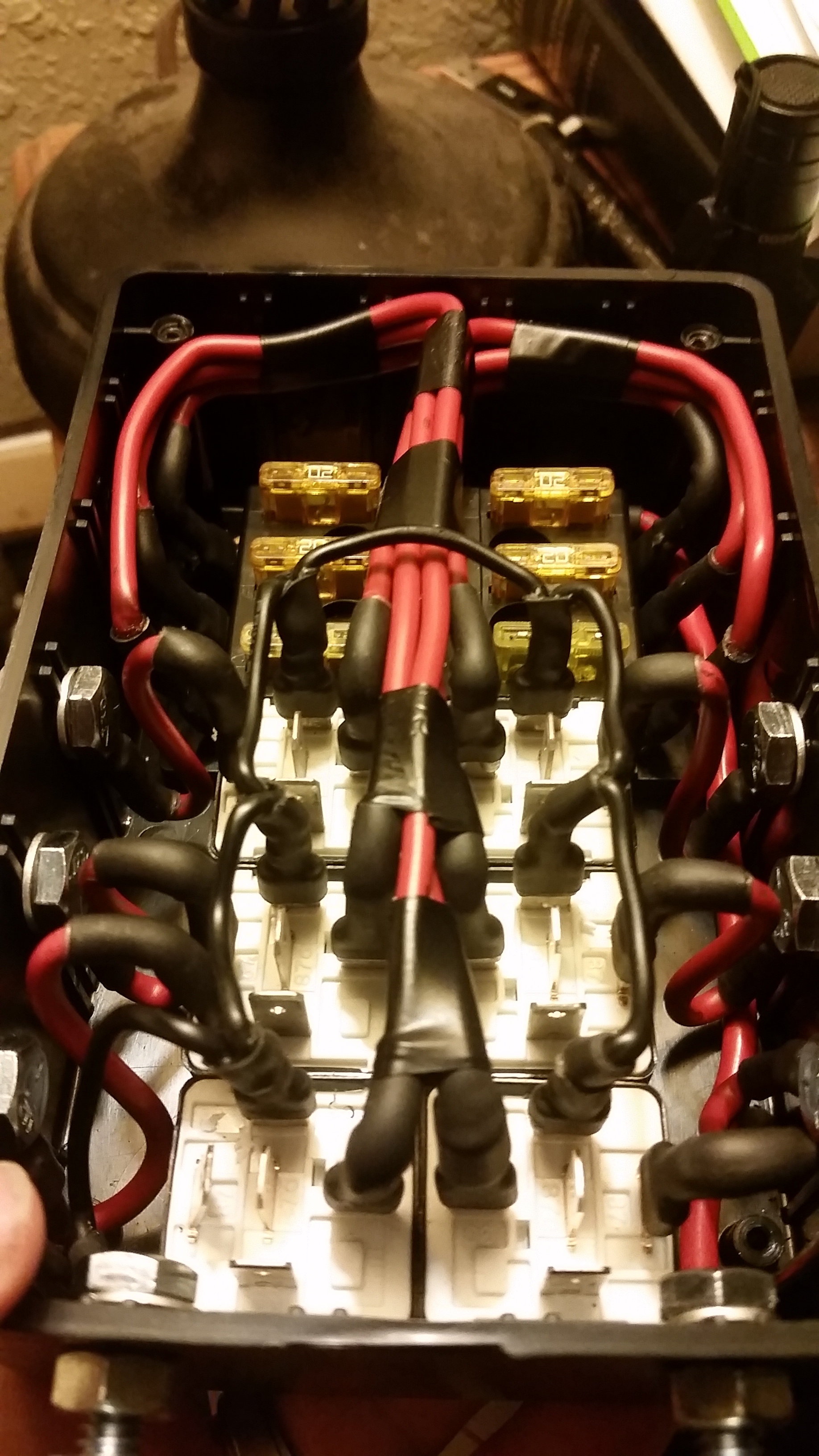
I just skimmed through your thread but I didn't see mention of your relay mounting method.
To keep things clean I suggest that you build a fitchbox.
It really cleans up the install.
Look it up. Lots of threads on the subject.
Your fusing that you have between the toggle and relay are completely unnecessary. All the current will be carried across the relay. You can use Cat5 networking cable to run from the toggles to the relays to trigger the relays when the toggles are turned on. That alone will save you a ton of money on wire.
Same goes with the 12v supply to the toggles. No need for large wires there. Small 16 gauge wire will do.
Here's my fitch box with 6 relays and a 6 gang fuse panel.
Last edited by Lowrange2; 02-23-2015 at 02:55 PM.
02-23-2015, 03:53 PM
#13
Member
Thread Starter
Join Date: May 2011
Location: Olympia WA
Posts: 142
Likes: 0
Received 0 Likes
on
0 Posts
Year: 1994
Model: Cherokee
Engine: 4.0
I just skimmed through your thread but I didn't see mention of your relay mounting method.
To keep things clean I suggest that you build a fitchbox.
It really cleans up the install.
Look it up. Lots of threads on the subject.
Your fusing that you have between the toggle and relay are completely unnecessary. All the current will be carried across the relay. You can use Cat5 networking cable to run from the toggles to the relays to trigger the relays when the toggles are turned on. That alone will save you a ton of money on wire.
Same goes with the 12v supply to the toggles. No need for large wires there. Small 16 gauge wire will do.
Here's my fitch box with 6 relays and a 6 gang fuse panel.
To keep things clean I suggest that you build a fitchbox.
It really cleans up the install.
Look it up. Lots of threads on the subject.
Your fusing that you have between the toggle and relay are completely unnecessary. All the current will be carried across the relay. You can use Cat5 networking cable to run from the toggles to the relays to trigger the relays when the toggles are turned on. That alone will save you a ton of money on wire.
Same goes with the 12v supply to the toggles. No need for large wires there. Small 16 gauge wire will do.
Here's my fitch box with 6 relays and a 6 gang fuse panel.
02-27-2015, 03:59 PM
#15
CF Veteran
How do you replace a relay if it goes bad mounted in the box like that? Wouldn't you want the tops of the relays exposed, to pull straight up and out, with the wires underneath?