Homebrew LED front turn signals ('84-'96)
 11-21-2011, 11:44 PM
#1
CF Veteran
Thread Starter
Join Date: Apr 2011
Location: Clayton, NC
Posts: 1,146
Likes: 0
Received 0 Likes
on
0 Posts
Year: 1988
Model: Cherokee
Engine: 4.6L I6 Stroker with port matched +99 intake and 62mm TB
Ever wanted to modify your XJ to have a more modern look while still being a sick trail rig? Or maybe you hate that one side always seems to be brighter or blinks faster than the other… Regardless of what your motivation is, you’re reading this for a reason so listen close lol. 
To start with, I want to share my reasoning behind this modification to my rig. My XJ is an ’88 and had some strange stuff going on with the lighting system. My bulbs were never the same brightness and the flash rate for driver side vs passenger side were different. No matter what I did, this was a problem and I ultimately got sick of it. Instead of spending tons of money trying to diagnose the problem, I went with a cooler option that was sparked via classes I was taking in school at the time. So let’s get to the nitty-gritty.
What you’ll need: ***Note: Order a few extras of each part for back up in case you fry or lose something.
Now that everything is figured out, I simulated this circuit in MultiSim:

Now let’s turn a virtual representation into a tangible, working model. I started out by placing the LEDs on perf-board, orienting them in the same direction and then bending the anode and cathode accordingly. This makes for a consistent built circuit and prevents wiring them incorrectly which will lead to no light and head scratching. Next, I placed the resistors and diodes.

The 7808 voltage regulators were placed that the top of the board, one for turn signaling and one for parking lights. I don’t have a close up picture of this, but you can see this is some of the following pictures. Also, I soldered long, stranded wires to the circuit from the back. Black goes to ground, which is common for both bright and dim circuitry. I used yellow for bright turn signals and red for dim parking lights. MAKE SURE that you keep track of what color wires you use and to which wires they’ll tie into later when you attach them to your XJ. Also, these wires will be routed out of the bulb socket hole in the back of the housing. WARNING: If you wire these with the wrong polarity, YOU WILL fry the voltage regulators and that hard work you did water-proofing them will prove to be a b*tch when you have to go back to replace and re-solder in a new regulator. Make sure you know which wire is your ground.
In the picture and video below, I’m testing the design to ensure it works as anticipated.

CLICK FOR VIDEO
Okay, so everything works. Now it’s time to water-proof them and paint to make it more reflective and nicer looking once they’re within the housing. A hot-glue gun will be your best bet here. It dries quickly, it can seep into the nooks and crannies pretty well, and it’s a good insulator. Be sure to cover all electrical connections with hot-glue. That means front and back! Be moderate with it, overkill here will accomplish nothing other than potential clearance issues when you go to install them in the housing later. Once the hot-glue is done hardening and you’ve removed all the stray glue strings that come with it, it’s time for that shiny silver paint. Be sure to cover the LEDs and voltage regulators with tape of some sort. I sprayed two coats for an even coverage.

Now, you can place them into the housing. If it wasn’t clear, you need to carefully separate the lens from the reflector housing. Get a spare set from the junkyard if you’re not comfortable messing with yours. They’re cheap enough that you shouldn’t be too worried. Set them in there and put the lens back on. Play around with it and make sure the LEDs aren’t pressed up against the lens too badly. If so, you’ve put on too much hot-glue on the back solder joints or the LEDs aren’t sat down as far as they can go. I had to bend them all forward a little bit to make the lens sit flush again. They’re pretty close to hitting, but they’ll be fine.

Now, once you’ve got them where you want them, tack some hot-glue on the back side of the board close to the outer edges and firmly seat them to the housing. After that, you need to quickly, but efficiently run a bead of hot-glue around the entire perimeter of the housing so you can re-bond the lens to it. If you’re not fast enough, the glue will dry and won’t bond. You may substitute hot-glue with any form of adhesive if you’d like. Once the lights are completed, you should have a product that looks similar to this:

Now you can install them in your XJ. I hope you labeled your wires and heeded my warning above. I can’t tell you which wires coming from your XJ correspond to turn signal and parking light, but what I can tell you is that a quick Google or forum search will yield you the information you seek for your year XJ. Now, assuming you wired it correctly, you should have something that looks like this now:


Well, that’s it… for this part at least. You’ll need to grab a new turn signal flasher relay from the parts store that is rated for LEDs or gives off a consistent flash regardless of burnt out bulbs or less current draw. It’s a 5-prong relay style flasher. It’s a direct replacement part for the Chrysler lighting system, but if you’re running an older AMC/Renix Jeep like me, you’ll have to do some simple modifications to replace both thermal flashers with this new, single flasher. More on that later in another write-up. If y’all have any further questions, PM me. I’ll be glad to help.
To start with, I want to share my reasoning behind this modification to my rig. My XJ is an ’88 and had some strange stuff going on with the lighting system. My bulbs were never the same brightness and the flash rate for driver side vs passenger side were different. No matter what I did, this was a problem and I ultimately got sick of it. Instead of spending tons of money trying to diagnose the problem, I went with a cooler option that was sparked via classes I was taking in school at the time. So let’s get to the nitty-gritty.
What you’ll need: ***Note: Order a few extras of each part for back up in case you fry or lose something.
- 54 – 8mm Super bright yellow LEDs (Rated: 2.2V DC / 100mA) <http://www.elexp.com/opt_8r4d.htm>
- 20 – 15 ohm, � watt resistors
- 20 – 56 ohm, � watt resistors
- 4 – 7808 (8V DC/1000mA) positive voltage regulator
- 4 – TO-220 heatsink & bolts
- 36 – 1N4001 diode
- Perf-board (enough to cut and fit into turn signal housing)
- Hot-glue gun & hot-glue sticks (or comparable quick dry insulator)
- Silver glitter spray paint
- Solder, liquid or paste flux, and soldering iron of course
Now that everything is figured out, I simulated this circuit in MultiSim:
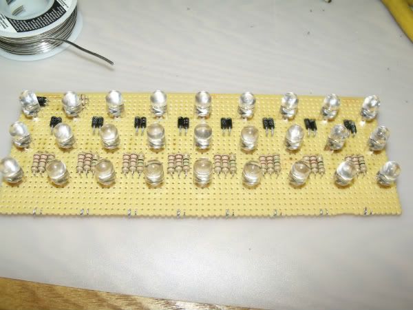
Now let’s turn a virtual representation into a tangible, working model. I started out by placing the LEDs on perf-board, orienting them in the same direction and then bending the anode and cathode accordingly. This makes for a consistent built circuit and prevents wiring them incorrectly which will lead to no light and head scratching. Next, I placed the resistors and diodes.
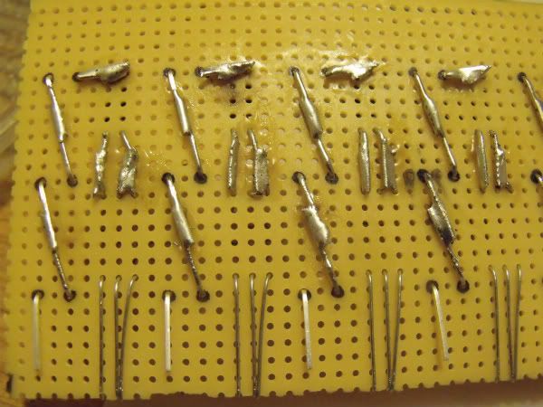
The 7808 voltage regulators were placed that the top of the board, one for turn signaling and one for parking lights. I don’t have a close up picture of this, but you can see this is some of the following pictures. Also, I soldered long, stranded wires to the circuit from the back. Black goes to ground, which is common for both bright and dim circuitry. I used yellow for bright turn signals and red for dim parking lights. MAKE SURE that you keep track of what color wires you use and to which wires they’ll tie into later when you attach them to your XJ. Also, these wires will be routed out of the bulb socket hole in the back of the housing. WARNING: If you wire these with the wrong polarity, YOU WILL fry the voltage regulators and that hard work you did water-proofing them will prove to be a b*tch when you have to go back to replace and re-solder in a new regulator. Make sure you know which wire is your ground.
In the picture and video below, I’m testing the design to ensure it works as anticipated.
CLICK FOR VIDEO
Okay, so everything works. Now it’s time to water-proof them and paint to make it more reflective and nicer looking once they’re within the housing. A hot-glue gun will be your best bet here. It dries quickly, it can seep into the nooks and crannies pretty well, and it’s a good insulator. Be sure to cover all electrical connections with hot-glue. That means front and back! Be moderate with it, overkill here will accomplish nothing other than potential clearance issues when you go to install them in the housing later. Once the hot-glue is done hardening and you’ve removed all the stray glue strings that come with it, it’s time for that shiny silver paint. Be sure to cover the LEDs and voltage regulators with tape of some sort. I sprayed two coats for an even coverage.
Now, you can place them into the housing. If it wasn’t clear, you need to carefully separate the lens from the reflector housing. Get a spare set from the junkyard if you’re not comfortable messing with yours. They’re cheap enough that you shouldn’t be too worried. Set them in there and put the lens back on. Play around with it and make sure the LEDs aren’t pressed up against the lens too badly. If so, you’ve put on too much hot-glue on the back solder joints or the LEDs aren’t sat down as far as they can go. I had to bend them all forward a little bit to make the lens sit flush again. They’re pretty close to hitting, but they’ll be fine.
Now, once you’ve got them where you want them, tack some hot-glue on the back side of the board close to the outer edges and firmly seat them to the housing. After that, you need to quickly, but efficiently run a bead of hot-glue around the entire perimeter of the housing so you can re-bond the lens to it. If you’re not fast enough, the glue will dry and won’t bond. You may substitute hot-glue with any form of adhesive if you’d like. Once the lights are completed, you should have a product that looks similar to this:
Now you can install them in your XJ. I hope you labeled your wires and heeded my warning above. I can’t tell you which wires coming from your XJ correspond to turn signal and parking light, but what I can tell you is that a quick Google or forum search will yield you the information you seek for your year XJ. Now, assuming you wired it correctly, you should have something that looks like this now:
Well, that’s it… for this part at least. You’ll need to grab a new turn signal flasher relay from the parts store that is rated for LEDs or gives off a consistent flash regardless of burnt out bulbs or less current draw. It’s a 5-prong relay style flasher. It’s a direct replacement part for the Chrysler lighting system, but if you’re running an older AMC/Renix Jeep like me, you’ll have to do some simple modifications to replace both thermal flashers with this new, single flasher. More on that later in another write-up. If y’all have any further questions, PM me. I’ll be glad to help.
Last edited by onlyinajeep726; 11-22-2011 at 03:19 PM.


Thread
Thread Starter
Forum
Replies
Last Post
BayArea93xj
Stock XJ Cherokee Tech. All XJ Non-modified/stock questions go here
8
06-11-2016 10:43 AM
Whjs416
Stock Grand Cherokee Tech. All ZJ/WJ/WK Non-modified/stock questions go here!
0
08-29-2015 10:12 AM
rusty_bucket
Stock XJ Cherokee Tech. All XJ Non-modified/stock questions go here
3
08-29-2015 06:42 AM
CCKen
Stock XJ Cherokee Tech. All XJ Non-modified/stock questions go here
3
08-20-2015 08:07 PM
Currently Active Users Viewing This Thread: 1 (0 members and 1 guests)