When you click on links to various merchants on this site and make a purchase, this can result in this site earning a commission. Affiliate programs and affiliations include, but are not limited to, the eBay Partner Network.
Stock XJ Cherokee Tech. All XJ Non-modified/stock questions go hereXJ (84-01)
All OEM related XJ specific tech. Examples, no start, general maintenance or anything that's stock.
first of all
i`m not an author of a software so software are designed by (С) Konstantin Grjznov Also used info from:
jeep.avtograd.ru
jeep-forum.ru
Renix manual: http://jeep.avtograd.ru/Cherokee/inj.../89JeepEFI.pdf
So, renix ECU based on two core Motorolla ecu (also used for first garage - made apple PC)
renix ecu do not collect errors but it is adapted and collect some data to correct stock pre-defined values.
ecu operate in few modes based and in different mode it used info form some of sensors, other sensors ignored
1) key-in Mode(engine not started yet)
Ecu use info from : MAP,MAT,CTS, TPS and batt voltage
In this mode ecu connect ground to b+ relay for 1-3 sec and fuel pump add fuel to a fuel rail, also ecu enable o2 heater relay and o2 sensor prepared to start
2) Crank mode
Ecu use info from :CPS, MAT, MAP,SYNC sensor in distributor, TPS, startter relay(for AUTO trans only),Batt voltage.
In this case, the ballast resistor is shorted during startup. ECU energizes the fuel pump relay and fuel pump starts working.
ECU turns the system EGR (Exhaust Gas Recirculation. EGR), activating EGR-solenoid. Voltage applied to the nozzle and the ECU controls the pulse width by adjusting the length of time that the injector is energized.
Based on the testimony of the crankshaft speed sensor, ECU determines the correct ignition timing and applies voltage to the ignition coil.
On all injectors voltage is applied at the same time, once a complete revolution of the crankshaft, with the exception of a cold start, when the voltage on the injectors fed twice per revolution of the crankshaft. This increased supply of fuel lasts for a few seconds after starting. To avoid excess fuel, ECU limits the number of times the nozzle opening two times per revolution of the crankshaft. This limit is calculated based on the coolant temperature. If the temperature is very low, ECU increases the number of times the nozzle opening twice.
When the ignition key is turned to position START, Alarm when running is sent to ECU. If the vehicle is equipped with an automatic transmission, the starter relay does not transmit the signal to the ECU, if the automatic transmission is not in the Park or Neutral.
ECU thinks the startup mode completed as soon as the engine speed was 400 rpm
3) warm-up mode
Ecu use info from :CPS, MAT,MAP, CTS,SYNC sensor in distributor, TPS, startter relay(for AUTO trans only),Batt voltage,detonation sensor(shock sensor),AC reley
ECU turns the system EGR (Exhaust Gas Recirculation. EGR), activating EGR-solenoid.
Voltage applied to the injectors and the ECU controls the length of time during which the voltage is applied to the injector. On all jets voltage is applied at the same time, once a complete revolution of the crankshaft. ECU also provides the correct idle speed, giving the correct voltage to theidle stepper motor. If necessary, the idle speed is also regulated to compensate for the increased load on the engine from the compressor on the air conditioner (if present).
In addition to the above, ECU determines the correct ignition timing and controls the ignition module. ECU includes the transmission shift indicator, if the engine speed and load guarantee operation at a higher gear.
4) Idle Mode
At idle, ECU analyzes the signals:
from the MAP sensor
engine speed sensor,
The air temperature sensor (MAT);
the sensor synchronization;
coolant temperature sensor (CTS);
throttle position sensor (TPS),
the voltage on the battery,
the signal from the oxygen sensor
signal conditioner switch (if the unit is present)
with the knock sensor.
ECU turns the system EGR (Exhaust Gas Recirculation. EGR), activating EGR-solenoid.
Voltage applied to the injectors and the ECU controls the pulse width by adjusting the length of time that the injector is energized. On all jets voltage is applied at the same time, once a complete revolution of the crankshaft. ECU also provides the correct idle speed, giving the correct voltage to the idle stepper motor. If necessary, the idle speed is also regulated to compensate for the increased load on the engine from the compressor on the air conditioner (if present).
In addition to the above, ECU determines the correct ignition timing and controls the ignition module.
By monitoring the oxygen sensor readings, ECU adjusts the width of the pulse applied to the nozzle to achieve the optimal composition of the fuel mixture 14,7:1.
5)Cruise mode While cruising, ECU analyzes the signals:
from the MAP sensor
engine speed sensor,
The air temperature sensor (MAT);
the sensor synchronization;
coolant temperature sensor (CTS);
throttle position sensor (TPS),
the voltage on the battery,
the signal from the oxygen sensor
with knock sensor
signal conditioner switch (if the unit is present).
ECU breaks the "mass" in the EGR-solenoid, including the way the exhaust gas recirculation system to reduce toxicity (EGR).
Fuel supply and injector control in this mode is similar to idle.
6) Deceleration mode
In the engine braking, ECU analyzes the signals:
from the MAP sensor
engine speed sensor,
air temperature sensor (MAT);
the sensor synchronization;
coolant temperature sensor (CTS);
throttle position sensor (TPS),
signal conditioner switch (if the unit is present).
ECU turns the system EGR (Exhaust Gas Recirculation. EGR), activating EGR-solenoid. Voltage applied to the injectors and the ECU controls the pulse width by adjusting the length of time that the injector is energized.
ECU determines the correct ignition timing and controls the ignition module.
If the ECU has received a signal to close the throttle and the engine speed with the above 1500 rpm, ECU concludes that carried off the engine braking and fuel injection system. Powered fuel injection is resumed as soon as the engine speed will be less than 1500 rpm
7) WOT(wide open throttle) mode
While maximizing power, ECU analyzes:
signals from the MAP sensor
engine speed sensor,
The air temperature sensor (MAT);
the sensor synchronization;
coolant temperature sensor (CTS);
the voltage on the battery
the signal from the knock sensor.
Barometric pressure value stored in the computer at startup, updated. ECU turns the system EGR (Exhaust Gas Recirculation. EGR), activating EGR-solenoid. ECU controls the pulse width by adjusting the length of time that the injector is energized.
ECU determines the correct ignition timing and controls the ignition module. If any cylinder detonation is detected, ECU lowers the ignition timing in the cylinder until no detonation, returning to the values on which the engine is running to detect detonation.
Because for diagnosis described below, only two contacts, in fact no matter what kind of car, with or without ABS (and no one, and no promises).
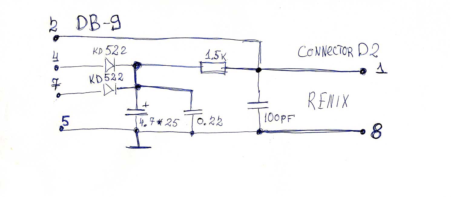
Use as an earthy, terminal 8 D2 (Земля sensors)
Experiments with other earth terminals to no good no avail.
And as a signal using the output of one connector D2 (Diagnosis computer.)
Output 1 connector D2 is an open collector transistor, as indicated in the diagram C12 TX_OUT, it must be connected through a resistor about 1.5 K Power at 5 volts.
 10-24-2012, 02:39 AM